
Filling and packaging machine and process for producing package

Active Publication Date: 2010-02-25
ORIHIRO ENGINEERING CO LTD
View PDF11 Cites 7 Cited by
  • Summary
  • Abstract
  • Description
  • Claims
  • Application Information

AI Technical Summary

Benefits of technology

[0014]It is a first object of the present invention to provide a vertical-type filling and packaging machine which can produce packages efficiently by minimizing the time period in which feeding of a film is stopped, and a method of producing packages.
[0017]Since the cooling bars are adapted to be movable in the vertical direction in this manner, the cooling bars can cool and solidify the portion of the film heat-sealed by the seal bars while the film is fed downward. This can reduce the time period in which the feeding of the film is stopped as compared with the conventional example. In addition, the seal bars do not need to be moved in the vertical direction during the operation of the filling and packaging machine, so that it is possible to shorten the time period for switching from the cooling bars to the seal bars in the transition to the next heat-sealing step subsequent to the completion of the cooling operation of the film.
[0018]In the filling and packaging machine of the present invention, the seal bars do not need to be moved in the vertical direction as described above. Thus, when each of the cooling bars is supported by an upper portion of a support member placed below the seal bars and extended in the vertical direction to be movable in a direction in which the support members are opposite to each other and in the vertical direction, a pair of film holders opening or closing to sandwich the film from the sides can be placed between the supply pipe and the seal bars. The film holders can control dropping of the contents below the film holders. When the film is heat-sealed by the seal bars with the film holders closed, the heat sealing of the film can be performed more stably without being affected by the contents. Since the heat sealing of the film can be performed without being affected by the contents, the contents can be supplied even during the heat sealing of the film, thereby improving the manufacture efficiency of the package.
[0020]As described above, in the method of producing a package according to the present invention, the cooling bars sandwiching the film are moved downward at the same speed as the feeding speed of the film while the film is fed downward. Since the heat-sealed portion of the film is cooled while the film is moved downward, the time period in which the feeding of the film is stopped is reduced as compared with the conventional example.
[0021]As described above, according to the present invention, the heat-sealed film can be cooled during the feeding of the film to reduce the time period in which the feeding of the film is stopped, thereby enabling efficient manufacture of the packages. Since the seal bars for heat-sealing the film do not need to be moved vertically, the film holders can be placed above the seal bars. As a result, the contents can be supplied continuously during the heat-sealing operation of the film by the seal bars to improve the manufacture efficiency of the package.

Problems solved by technology

This causes the cooling bars to move and pressurize the heat-sealed portion of the film.
Such a horizontal seal mechanism, however, has a complicated structure which limits the usable shapes in the seal bars and the cooling bars to some extent.
If the usable shapes of the seal bars and the cooling bars are limited, a wide variety of packages cannot be produced.
Even when the film holders are provided for the horizontal seal mechanism, the film holders cannot be functioned effectively since the film holders need to be opened in the upward movement of the horizontal seal mechanism.
In this case, however, the film holders need to be placed at a level determined by taking account of the upward moving distance of the horizontal seal mechanism, leading to an increase in the height of the filling and packaging machine.

Method used


Image

  • Filling and packaging machine and process for producing package
  • Filling and packaging machine and process for producing package
  • Filling and packaging machine and process for producing package

Examples


Embodiment Construction

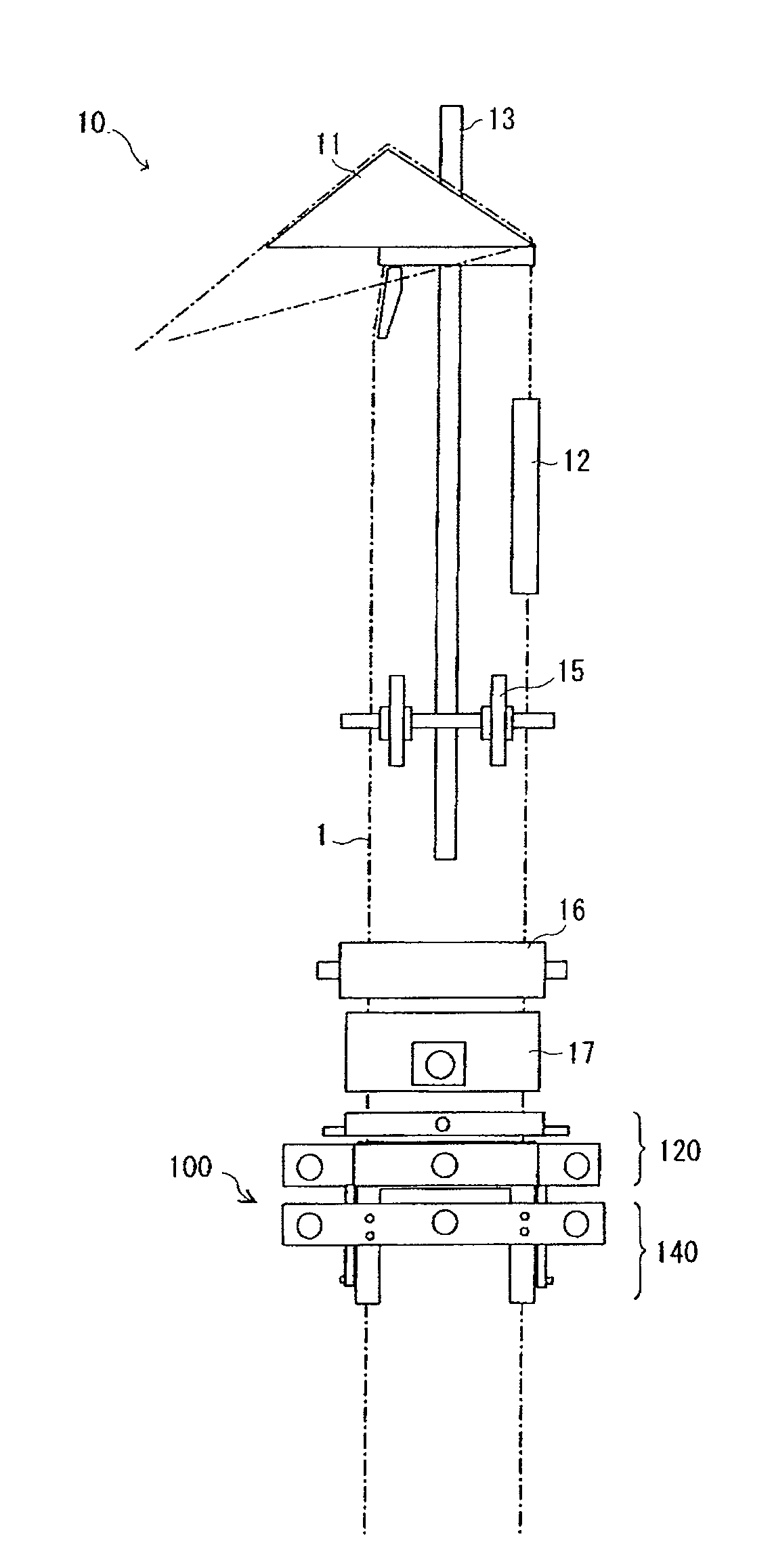
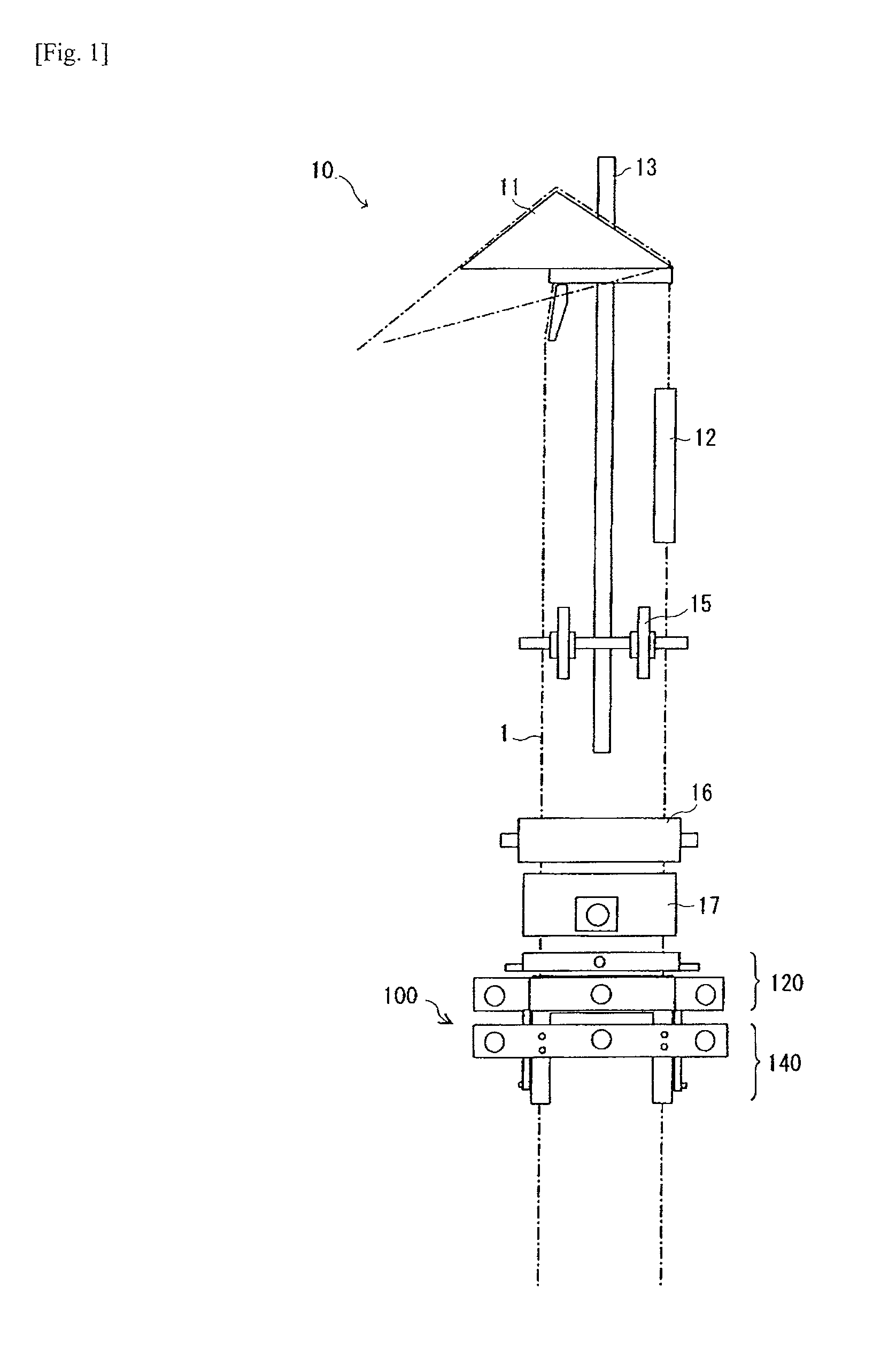
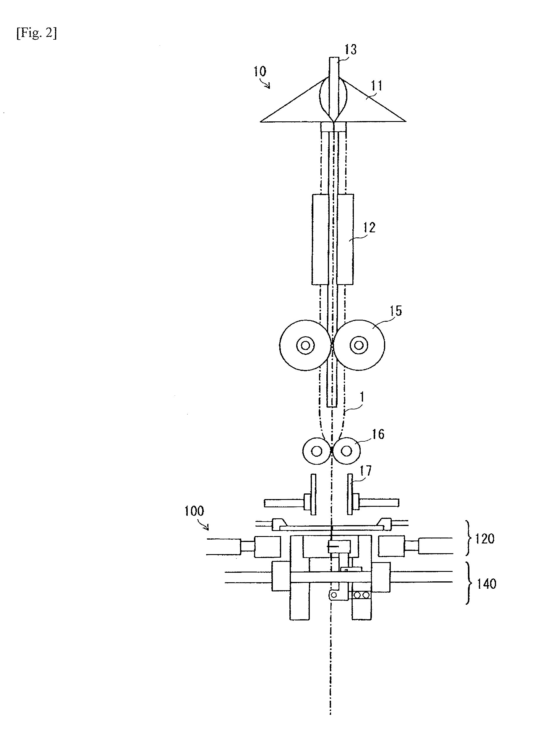
[0046]Referring to FIGS. 1 and 2, filling and packaging machine 10 according to an embodiment of the present invention is shown which has bag forming guide 11, vertical seal mechanism 12, supply pipe 13, a pair of squeeze rollers 16, and horizontal seal mechanism 100. In FIGS. 1 and 2, driving portions of vertical seal mechanism 12, squeeze rollers 16, horizontal seal mechanism 100 and the like are omitted for simplifying the drawings.

[0047]Bag forming guide 11 forms a long length of film 1 of sheet shape fed out of a roll (not shown) by folding film 1 in half along its longitudinal direction to align both edges thereof while guiding film 11 downward. Auxiliary feed roller 15 is placed under bag forming guide 11 to assist the feeding of film 1 from upward to downward.

[0048]Vertical seal mechanism 12 is placed between bag forming guide 11 and auxiliary feed roller 15. Vertical seal mechanism 12 has a pair of vertical seal bars disposed opposite to each other across a path through whi...


PUM

PropertyMeasurementUnit
Sizeaaaaaaaaaa
Speedaaaaaaaaaa
Widthaaaaaaaaaa

Abstract

Filling and packaging machine (10) includes supply pipe (13) for supplying contents into film (10), squeeze rollers (16) for feeding film (1) downward and horizontal seal mechanism (100) for sealing in the contents supplied into film (1). Horizontal seal mechanism (11) includes heating unit (120) having a pair of seal bars for heat-sealing film (1) and cooling / cutting unit (140), placed under the cooling / cutting unit, having a pair of cooling bars for cooling a heat-sealed portion of film 1. Cooling / cutting unit (140) is movable in a vertical direction so that the cooling bars can be positioned between the seal bars while the seal bars are opened.

Description

TECHNICAL FIELD[0001]The present invention relates to a vertical-type filling and packaging machine which successively produces packages including contents in the form of a liquid or a paste having no specific shape held within film, and to a method of producing packages of this type.BACKGROUND ART[0002]Vertical-type filling and packaging machines are known which produce packages including contents in the form of a liquid or a paste having no specific shape held therein.[0003]Such a vertical-type filling and packaging machine successively produces packages by forming a long length of sheet film such that both edges thereof in a width direction coincide and feeding the film downward. The vertical-type filling and packaging machine has a vertical seal mechanism which heat-seals the edges of the formed film along a longitudinal direction of the film to shape the film into a tubular shape, a supply pipe for supplying contents into the tubular shaped film, and a horizontal seal mechanism...

Claims


Application Information

Patent Timeline
IPC IPC(8): B65B51/10
CPCB29C65/18B29C66/836B29C65/745B29C66/0342B29C66/1122B29C66/4312B29C66/822B29C66/8221B29C66/8225B29C66/8491B29C2793/009B65B9/2007B65B9/213B65B51/303B65B51/32B29C65/74B29C66/8181B29C65/305B29C65/00B29C66/83221B29C66/8246B29C66/8161B29C65/7451B29C66/83543B29C66/8412B65B9/10B65B61/06B65B57/06
Inventor TSURUTA, ORIHIROYAMADA, SHUNJI
Owner ORIHIRO ENGINEERING CO LTD
Features
  • Generate Ideas
  • Intellectual Property
  • Life Sciences
  • Materials
  • Tech Scout
  • Unparalleled Data Quality
  • Higher Quality Content
  • 60% Fewer Hallucinations
Learn More