Angular velocity sensor

a technology of angular velocity and sensor, applied in the direction of acceleration measurement using interia force, turn-sensitive devices, instruments, etc., can solve the problems of output voltage generation, detection error, and inability to perform appropriate synchronous detection, so as to improve the detection accuracy of angular velocity and suppress the detection error of angular velocity

Inactive Publication Date: 2010-02-25
PANASONIC CORP
View PDF7 Cites 3 Cited by
  • Summary
  • Abstract
  • Description
  • Claims
  • Application Information

AI Technical Summary

Benefits of technology

[0022]According to the invention, the monitor electrode section and the sensing electrode section have the same capacitance value. For this reason, although the sensing signal that is output from the sensing electrode section and the monitor signal that is output from the monitor electrode section are phase-shifted, the sensing signal and the monitor signal can have the same phase shift amount with respect to a change in temperature. That is, since the sensing signal and the monitor signal have the same phase shift amount with respect to the change in temperature, even if the sensing signal is detected based on the monitor signal, a difference in the phase shift amount is not changed. As a result, it is possible to suppress a detection error of an angular velocity with respect to a change in temperature, and thus to improve detection accuracy of an angular velocity.

Problems solved by technology

As a result, appropriate synchronous detection cannot be performed.
That is, although no angular velocity component is generated in angular velocity signal 57, an output voltage is generated and becomes a detection error.

Method used


Image

  • Angular velocity sensor
  • Angular velocity sensor
  • Angular velocity sensor

Examples


Embodiment Construction

[0047]Hereinafter, an angular velocity sensor according to an embodiment of the invention will be described with reference to the drawings.

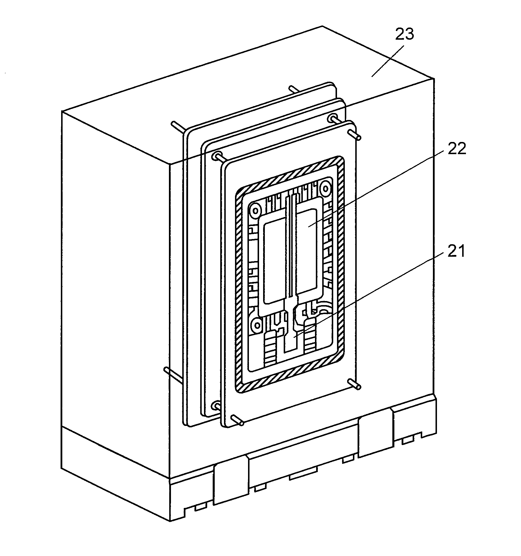
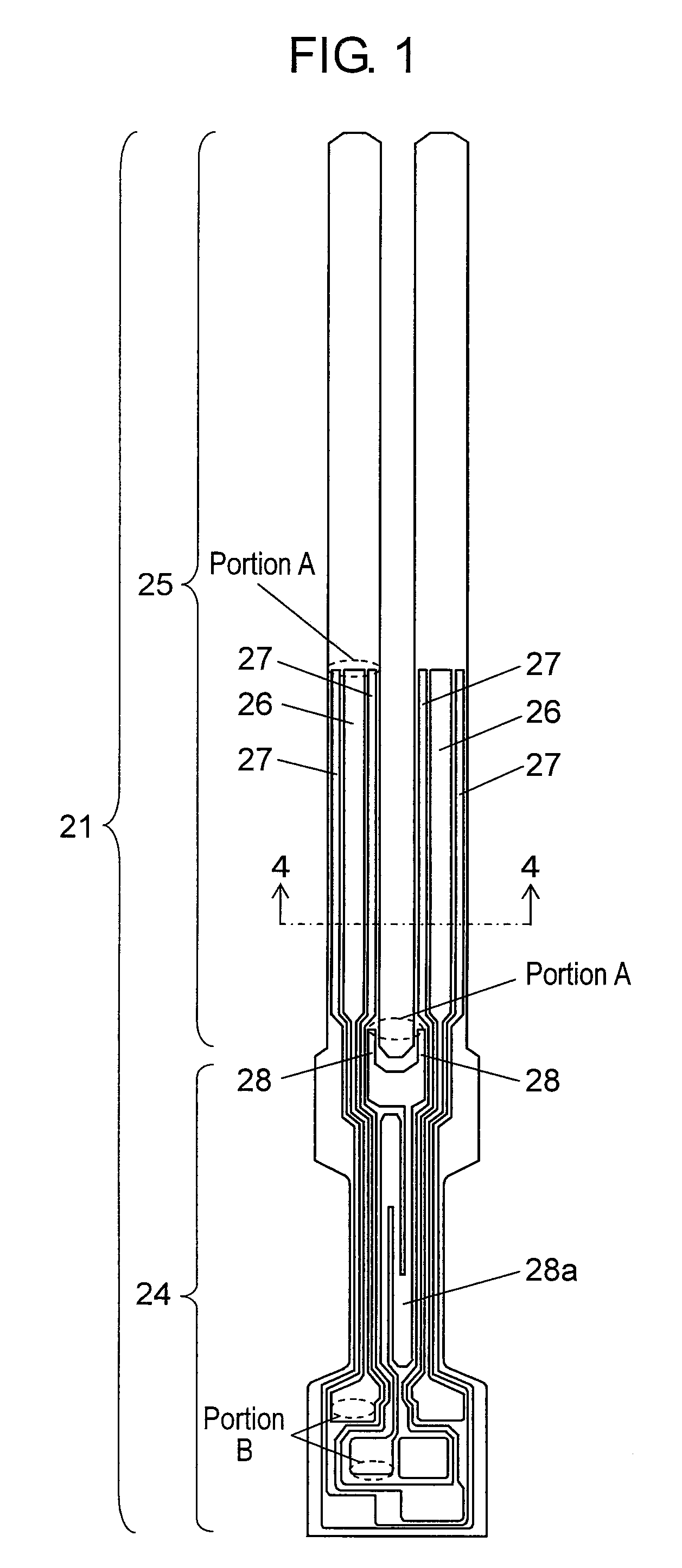
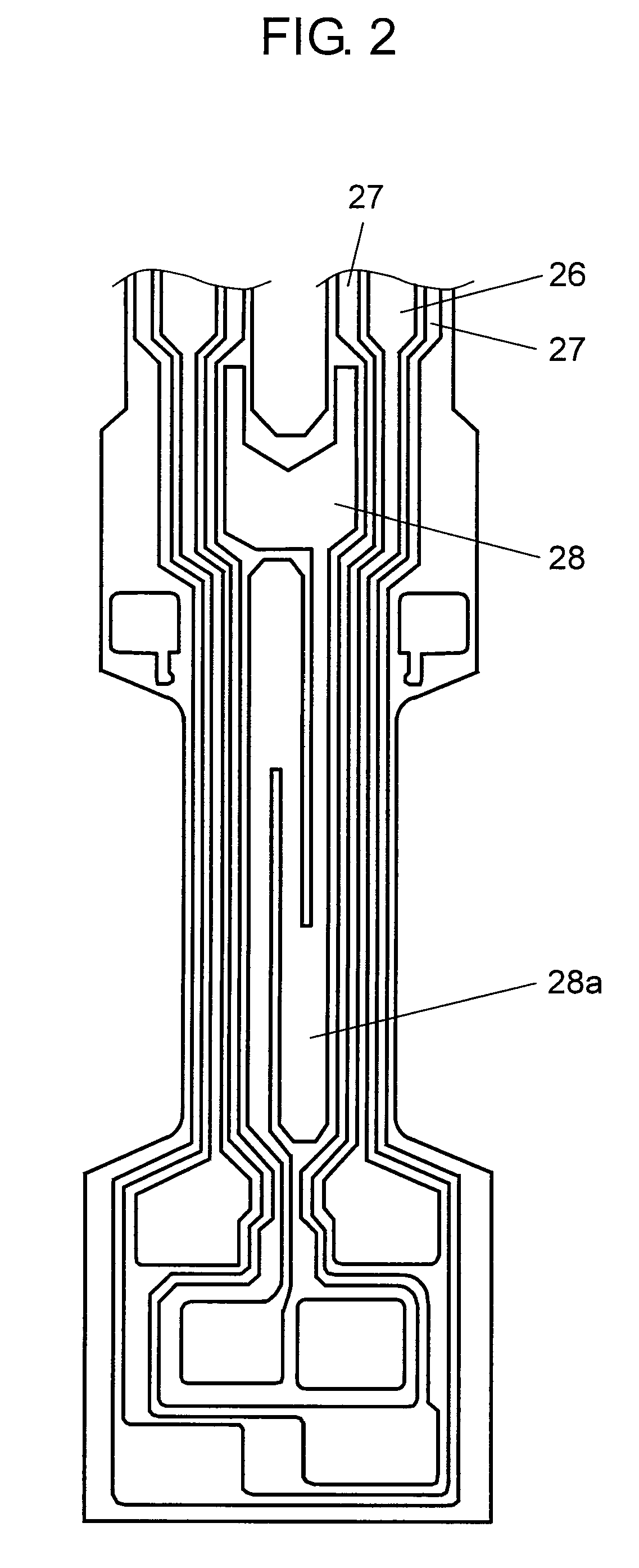
[0048]FIG. 1 is a plan view of a detecting element that is used in an angular velocity sensor according to an embodiment of the invention. FIG. 2 is an enlarged view of a shaft section of the detecting element. FIG. 3 is a partial perspective view of the angular velocity sensor.

[0049]In FIGS. 1 to 3, the angular velocity sensor of this embodiment includes detecting element 21 for angular velocity detection, electronic circuit 22 connected to detecting element 21, and case 23 housing detecting element 21 and electronic circuit 22.

[0050]Detecting element 21 has a tuning fork shape in which a pair of arm sections 25 are provided in shaft section 24. Detecting element 21 includes drive electrode section 26 and sensing electrode section 27 provided to extend from arm sections 25 to shaft section 24, and monitor electrode section 28 provided to extend ...


PUM


Abstract

An angular velocity sensor includes a drive electrode section (26) for inputting a drive signal for driving a detecting element (21), a monitor electrode section (28) detecting the drive status of the detecting element (21) and outputting a monitor signal, and a sensing electrode section (27) outputting a sensing signal, which is generated due to an angular velocity given to the detecting element (21). The drive electrode section (26), the monitor electrode section (28), and the sensing electrode section (27) each have a lower electrode formed on a substrate, a piezoelectric film formed of a piezoelectric material on the lower electrode, and an upper electrode formed on the piezoelectric film. The capacitance value between the upper and lower electrodes of the monitor electrode section (28) is set to be equal to the capacitance value between the upper and lower electrodes of the sensing electrode section (27), and the resistance value between both end portions of the monitor electrode section (28) is set to be equal to the resistance value between both end portions of the sensing electrode section (27).

Description

TECHNICAL FIELD [0001]The present invention relates to an angular velocity sensor adapted for use in various electronic apparatuses.BACKGROUND ART [0002]Hereinafter, a known angular velocity sensor will be described with reference to the drawings.[0003]FIG. 7 is a plan view of a detecting element which is used in a known angular velocity sensor. FIG. 8 is a sectional view of an arm section of a detecting element, which is used in the same angular velocity sensor, taken along the line 8-8.[0004]In FIGS. 7 and 8, the known angular velocity sensor has detecting element 1 for angular velocity detection, an electronic circuit (not shown) connected to detecting element 1, and a case (not shown) housing detecting element 1 and the electronic circuit.[0005]Detecting element 1 has a tuning fork shape in which a pair of arm sections 3 are provided in shaft section 2. Drive electrode section 4 and sensing electrode section 5 are provided to extend from arm sections 3 to shaft section 2. Monito...

Claims


Application Information

Patent Timeline
Patent Type & Authority Applications(United States)
IPC IPC(8): G01C19/56G01C19/5628H01L41/08H01L41/187
CPCH01L41/1132G01C19/5607H10N30/302
Inventor ASHIMORI, YOUHEI
Owner PANASONIC CORP
Why Eureka
Try Eureka