Electric equipment

a technology of electric equipment and equipment, applied in the direction of transformer/inductance magnetic core, instruments, measurement using digital techniques, etc., to achieve the effect of suppressing detection errors, simplifying the structure of electric equipment, and suppressing detection errors

Active Publication Date: 2020-05-26
HONDA MOTOR CO LTD
View PDF30 Cites 0 Cited by
  • Summary
  • Abstract
  • Description
  • Claims
  • Application Information

AI Technical Summary

Benefits of technology

[0009]The present invention has been made taking the above problem into account, and an object of the present invention is to provide electric equipment which makes it possible to suppress the detection error in an output signal outputted from an electric current sensor.
[0020]According to the present invention, it is possible to suppress the detection error in the output signal outputted from the electric current sensor.

Problems solved by technology

The problem of this type is not limited to the case of the Hall element, and is present as well also in the outputs from other detection elements.

Method used


Image

  • Electric equipment
  • Electric equipment
  • Electric equipment

Examples


embodiment

A. Embodiment

A-1. Structure

A-1-1. Overall Structure

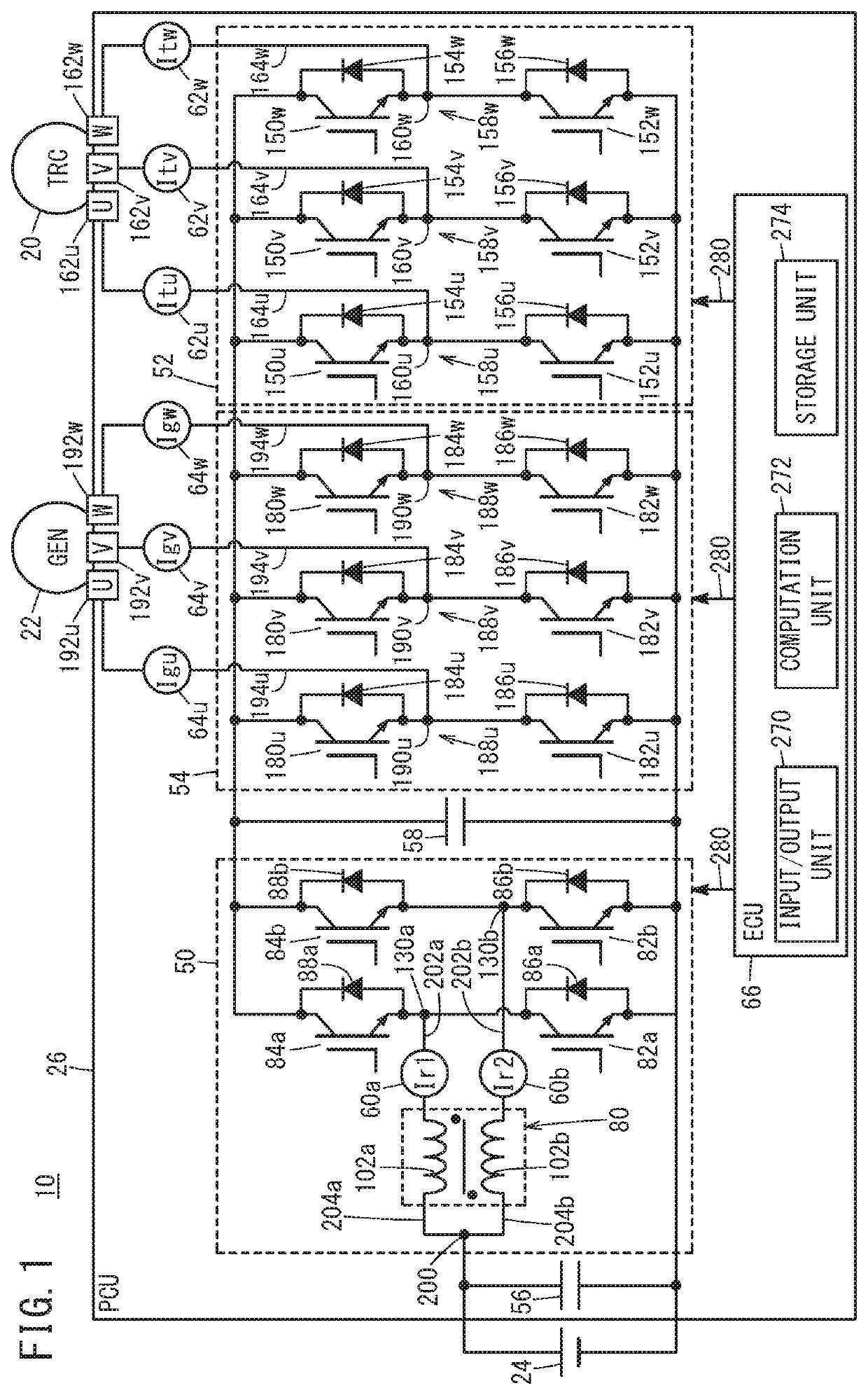
[0034]FIG. 1 is an electric circuit diaphragm schematically showing structure of a vehicle 10 including a power control unit 26 (hereinafter referred to as the “PCU 26”) as electric equipment according to one embodiment of the present invention. In addition to the PCU 26, the vehicle 10 includes a traction motor 20, a generator 22, and a high voltage battery 24 (hereinafter also referred to as the “battery 24” or “BAT 24”). The vehicle 10 is a hybrid vehicle. As a traction drive source, the vehicle 10 includes an engine (not shown) in addition to the traction motor 20. As described later, the vehicle 10 may be a vehicle of another type. The generator 22 performs power generation based on a drive force of the engine. The generator 22 may be used as the traction drive source.

[0035]The PCU 26 converts or adjusts electric power from the battery 24, and supplies the electric power to the traction motor 20. Further, the PCU 26 converts or...


PUM


Abstract

An electric current sensor of electric equipment includes a detection element, a reference voltage line to which a reference voltage signal is transmitted, an output signal line to which an output signal of the detection element is transmitted, and a ground line connected to a ground potential. The reference voltage line, the output signal line, and the ground line are bundled together by a cylindrical member which does not contain metal, and in this state, the reference voltage line, the output signal line, and the ground line are routed inside a casing containing a reactor, and connected to a control device.

Description

CROSS-REFERENCE TO RELATED APPLICATION[0001]This application is based upon and claims the benefit of priority from Japanese Patent Application No. 2017-108839 filed on May 31, 2017, the contents of which are incorporated herein by reference.BACKGROUND OF THE INVENTIONField of the Invention[0002]The present invention relates to electric equipment including an electric current sensor.Description of the Related Art[0003]Japanese Laid-Open Patent Publication No. 2010-197155 discloses a magnetic flux detection device 100 using a Hall element 10 (FIG. 1, paragraphs [0018], [0027]). The Hall element 10 at least includes a reference terminal tb, a power supply terminal td, and an output terminal “to” (paragraph [0024]). The reference terminal tb is used for setting a reference potential. Power supply voltage is applied to the power supply terminal td in a manner that magnetic flux Φ can be detected. The output terminal “to” outputs an output signal in correspondence with the detected magnet...

Claims


Application Information

Patent Timeline
Patent Type & Authority Patents(United States)
IPC IPC(8): G01R15/20G01R19/25G01R19/15
CPCG01R15/207G01R19/2513G01R15/202G01R19/15G01R19/00H01F27/26H01F27/30H02P27/06H02J7/2437Y02T10/92
Inventor OKAMOTO, NORIAKISHIMADA, MASAHIROKOCHI, NAOTOHASHINO, SATOSHIFUJITA, SATORU
Owner HONDA MOTOR CO LTD
Why Eureka
Try Eureka