Motion sensing program and electronic compass with motion sensing program

a technology of motion sensing and electronic compass, which is applied in the direction of indication/recording movement, navigation instruments, instruments, etc., can solve the problems of detection errors, inability to accurately execute motion sensing, and inability to accurately detect lifting up horizontally placed mobile terminal devices

Inactive Publication Date: 2011-10-25
ALPS ALPINE CO LTD
View PDF5 Cites 2 Cited by
  • Summary
  • Abstract
  • Description
  • Claims
  • Application Information

AI Technical Summary

Benefits of technology

[0010]The structure is capable of identifying the rotating direction to execute the accurate motion sensing without requiring such process as calibration. In the motion sensing program, the distance between two axes among X-, Y-, and Z-axis in the output coordinate is obtained, based on which the threshold determination is made to execute the motion sensing. This makes it possible to prevent the error of the motion sensing resulting from such micromotion as hand shaking, and the mere rotating operation.
[0011]In the step of determining with respect to execution of the motion sensing of the motion sensing program according to the present invention, preferably, the execution of the motion sensing is determined when a distance between a measurement starting point to a most distal measurement point from the measurement starting point in a coordinate of the specific biaxial output of the magnetic sensor is equal to or larger than a first predetermined value, and a distance between a measurement point resulting from substantially returning the magnetic sensor to a rotation starting position and the measurement starting point is equal to or smaller than a second predetermined value. Only when the reciprocated rotating operation is detected, it is determined that the motion sensing is executed. This makes it possible to suppress the detection error resulting from the involuntary action and the peripheral magnetic field.
[0017]The motion sensing program according to the present invention determines with respect to execution of the motion sensing based on the specific biaxial output of the magnetic sensor upon its rotation in a predetermined direction within a predetermined time period using at least biaxial output of the magnetic sensor. If execution of the motion sensing is determined, the rotating direction is identified. This makes it possible to execute accurate motion sensing without requiring such process as calibration.

Problems solved by technology

Otherwise the motion sensing cannot be executed accurately.
The “motion” involuntarily performed by the user in the normal use range, for example, lifting up the horizontally placed mobile terminal device is likely to be erroneously detected.
The detection error may also be caused by the magnetic source which moves around the device.

Method used


Image

  • Motion sensing program and electronic compass with motion sensing program
  • Motion sensing program and electronic compass with motion sensing program
  • Motion sensing program and electronic compass with motion sensing program

Examples


Embodiment Construction

[0025]An embodiment of the present invention will be described referring to the drawings.

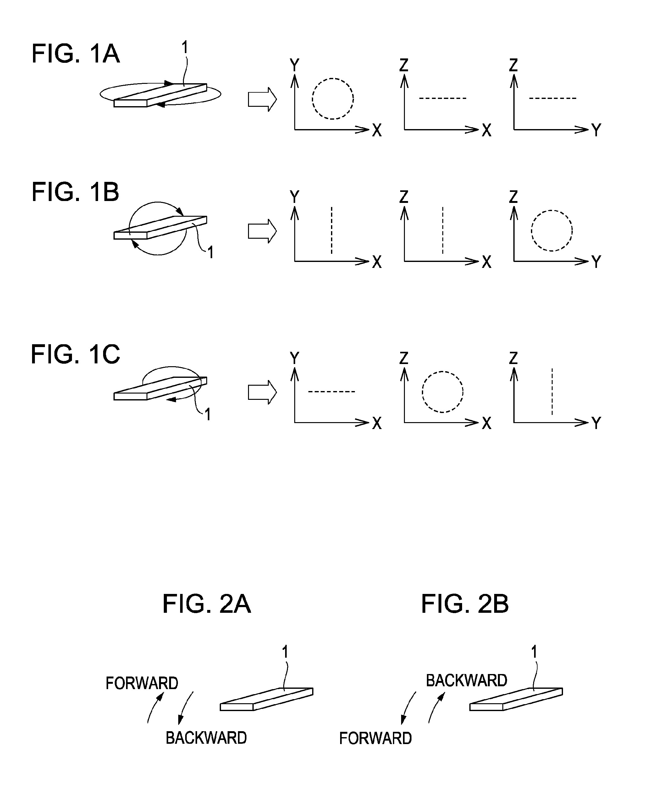
[0026]The motion sensing executed by the motion sensing program according to the present invention functions in sensing the motion upon rotation of the magnetic sensor in a predetermined direction. FIGS. 1A to 1C show respective rotating directions of the magnetic sensor. Specifically, FIG. 1A shows the state where a magnetic sensor 1 is rotated horizontally (rotation with respect to the vertical axis). FIG. 1B shows the state where the magnetic sensor 1 is rotated longitudinally (rotation with respect to the horizontal axis). FIG. 1C shows the state where the magnetic sensor 1 is rotated laterally (rotation with respect to the horizontal axis). Each state shown in FIGS. 1B and 1C represents the rotation with respect to the horizontal axis. In the case where the device having the magnetic sensor 1 installed therein (for example, mobile terminal device) has a substantially rectangular solid shape...


PUM


Abstract

A motion sensing program for executing a motion sensing based on at least a biaxial output of a magnetic sensor, which includes the steps of determining with respect to execution of the motion sensing based on the output of the specific biaxial output of the magnetic sensor upon its rotation in a predetermined direction, and identifying the rotating direction when execution of the motion sensing is determined.

Description

CLAIM OF PRIORITY[0001]This application is a Continuation of International Application No. PCT / JP2007 / 073505 filed on Dec. 5, 2007, which claims benefit of the Japanese Patent Application No. 2006-329034 filed on Dec. 6, 2006, which are hereby incorporated by reference.BACKGROUND OF THE INVENTION[0002]1. Field of the Invention[0003]The present invention relates to a motion sensing program for executing a motion sensing using a magnetic sensor for detecting geomagnetism, and an electronic compass having the motion sensing program installed therein.[0004]2. Description of the Related Art[0005]Recently, the mobile terminal device with a function for detecting tilted and shaken states of the main body of the device has been developed. The aforementioned mobile terminal device requires the tilt sensor for detecting the tilt angle of the tilted main body of the device, and the acceleration sensor for detecting the oscillation resulting from shaking of the main body of the device. There ha...

Claims


Application Information

Patent Timeline
Patent Type & Authority Patents(United States)
IPC IPC(8): G01C17/00G01B7/30G06F15/00
CPCG01C17/28G01P13/00G01P13/02G06F3/0346
Inventor HIROBE, KISEIKAWARADA, KATSUYUKI
Owner ALPS ALPINE CO LTD
Why Eureka
Try Eureka