Cutter head assembly for a wood planing machine

a wood planing machine and cutter head technology, which is applied in the direction of special profiling/shaping machines, flat surfacing machines, profiling/shaping machines, etc., can solve the problem of relative heavy load on the power motor of the wood planing machine, and achieve the effect of improving the cutting blade and minimizing the load

Inactive Publication Date: 2010-02-25
LIU CHIN YUAN
View PDF18 Cites 28 Cited by
  • Summary
  • Abstract
  • Description
  • Claims
  • Application Information

AI Technical Summary

Benefits of technology

[0008]An object of the present invention is to provide a cutter head assembly for a wood planing machine which has improved cutter blades to minimize the load on a power motor of the wood planing machine.

Problems solved by technology

However, such configurations of the cutter blades 3 result in relatively heavy load on a power motor of the wood planing machine.

Method used


Image

  • Cutter head assembly for a wood planing machine
  • Cutter head assembly for a wood planing machine
  • Cutter head assembly for a wood planing machine

Examples


Embodiment Construction

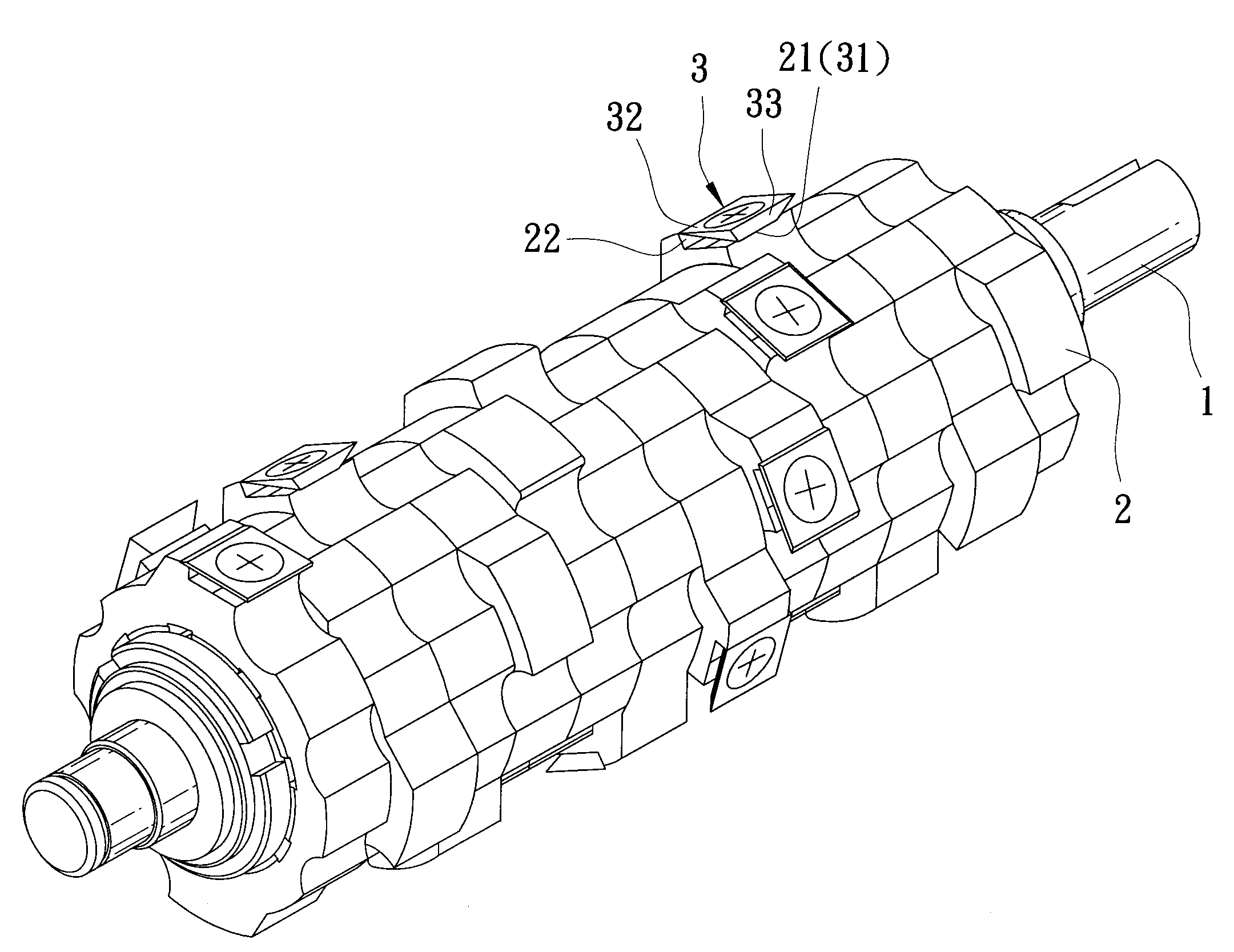
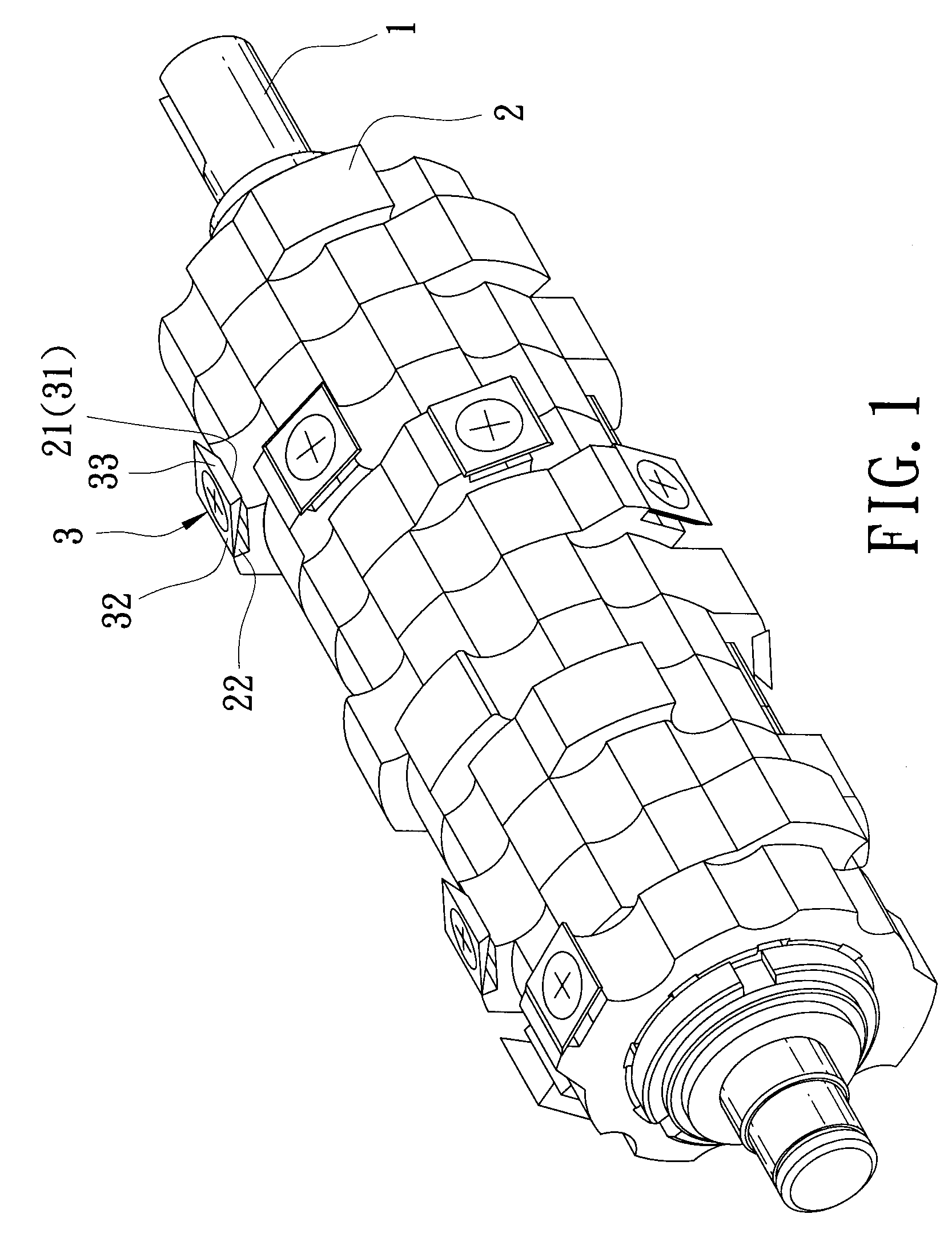
[0018]Referring to FIGS. 3 and 4, the preferred embodiment of a cutter head assembly for a wood planing machine according to the present invention is shown to comprise a rotary shaft 6, a plurality of blade carriers 4, a plurality of cutter blades 5, and a plurality of screw fasteners 7.

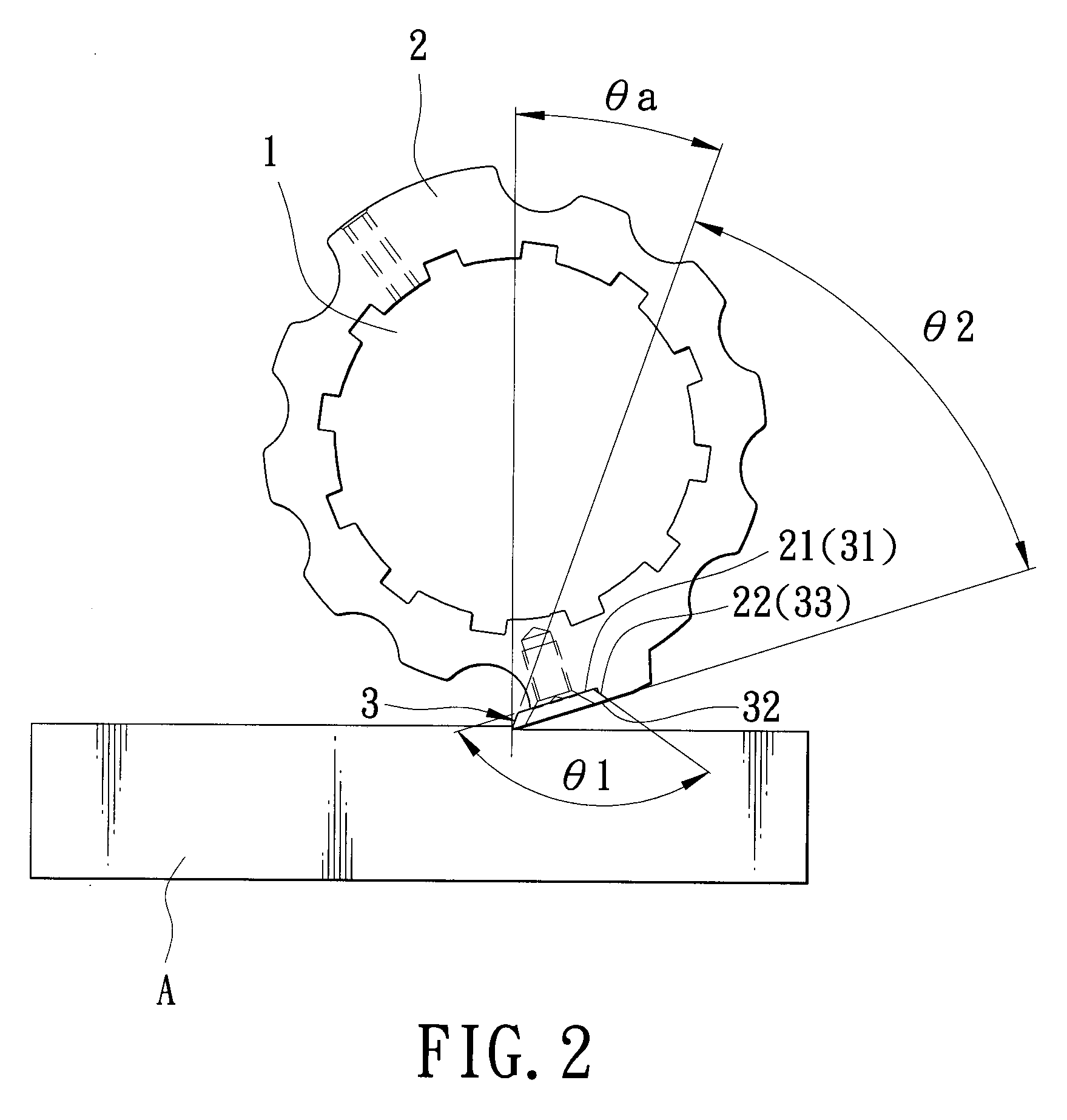
[0019]The rotary shaft 6 is elongated along and is rotatable about an axis. The blade carriers 4 are sleeved on and are non-rotatably retained on the shaft 6 along the axis. Each of the blade carriers 4 has an outer wall surface which includes a leading region 41 and a trailing region 42, which form a first included angle (θ1) therebetween. In this embodiment, the first included angle (θ1) is an obtuse angle. The cutter blades 5 are disposed to be secured on the outer wall surfaces of the blade carriers 4, respectively. Each of the cutter blades 5 has a first major wall surface 51 which has a first periphery and which is configured to abut against the leading region 41 of the respective blade carrier...


PUM


Abstract

A cutter head assembly for a wood planing machine includes a rotary shaft, a plurality of blade carriers non-rotatably retained on the shaft, and a plurality of cutter blades respectively secured on outer wall surfaces of the blade carriers by means of a plurality of screw fasteners. The outer wall surface of each blade carrier includes a leading region and a trailing region that form a first included angle of at least 90 degrees therebetween. Each blade has a first major wall surface abutting against the leading region, a second major wall surface disposed opposite to the first major wall surface, a cutting edge interposed between the first and second major wall surfaces and extending beyond the outer wall surface of the respective blade carrier, and an abutting edge disposed opposite to the cutting edge to abut against the trailing region. The cutting edge of each cutter blade intersects the second major wall surface at a second included angle ranging from 35 degrees to 45 degrees.

Description

CROSS-REFERENCE TO RELATED APPLICATION[0001]This application is a continuation-in-part of U.S. patent application Ser. No. 12 / 197,914, filed by the applicant on Aug. 25, 2008, the entire disclosure of which is incorporated herein by reference.BACKGROUND OF THE INVENTION[0002]1. Field of the Invention[0003]This invention relates to a cutter head assembly for a wood planing machine, more particularly to a cutter head assembly having a plurality of cutting blades for mounting on a rotary shaft of a wood planing machine so as to obtain a spiral cutting contour.[0004]2. Description of the Related Art[0005]Referring to FIGS. 1 and 2, in co-pending U.S. patent application Ser. No. 12 / 197,914, the applicant disclosed a cutter head assembly for a wood planing machine that includes a rotary shaft 1, a plurality of blade carriers 2 non-rotatably sleeved on the shaft 1, and a plurality of cutter blades 3 secured to the blade carriers 2 and arranged in a spiral manner. An outer wall surface of e...

Claims


Application Information

Patent Timeline
Patent Type & Authority Applications(United States)
IPC IPC(8): B27G13/04
CPCB27G13/04B27G13/005
Inventor LIU, CHIN-YUAN
Owner LIU CHIN YUAN
Why Eureka
Try Eureka