Ladder safety apparatus

Inactive Publication Date: 2010-02-25
M A CAMPESI FAMILY HLDG
View PDF15 Cites 13 Cited by
  • Summary
  • Abstract
  • Description
  • Claims
  • Application Information

AI Technical Summary

Benefits of technology

[0009]The slide body has a cam member with contact surfaces adapted for engaging serrations of the track member and slowing speed of an accidental fall. The contact surfaces of the slide member are similarly provided with serrations

Problems solved by technology

For example, it is believed that prior art harnesses have been difficult and time consuming for a person to initially put on prior to their ascent.
Additionally, after a person wearing a prior art harness became suspended by the rope grab and safety line, the suspe

Method used


Image

  • Ladder safety apparatus
  • Ladder safety apparatus
  • Ladder safety apparatus

Examples


Embodiment Construction

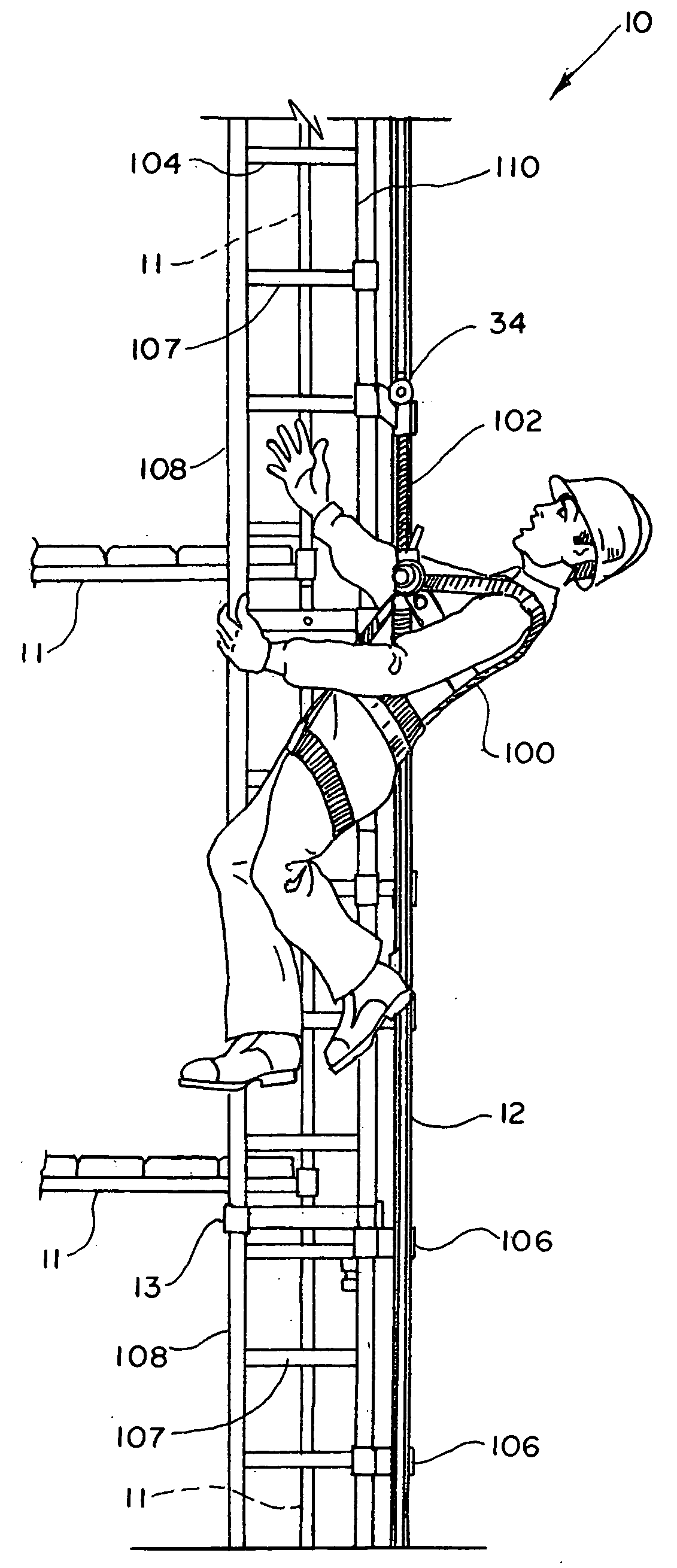
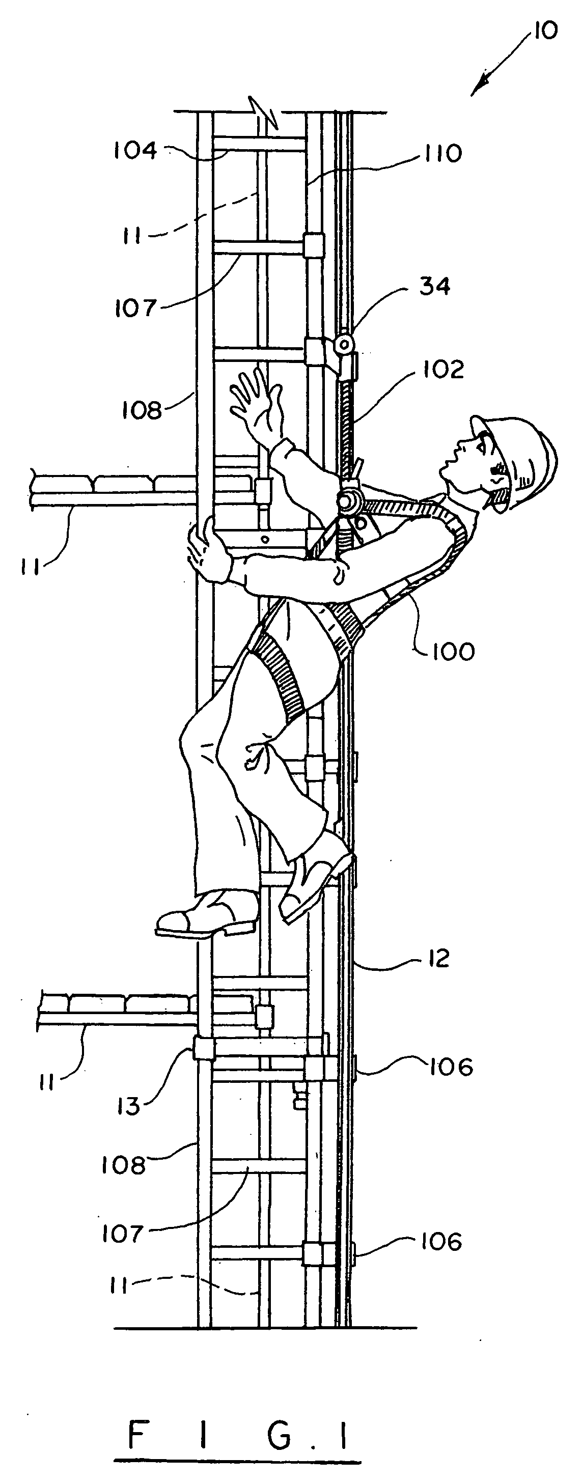
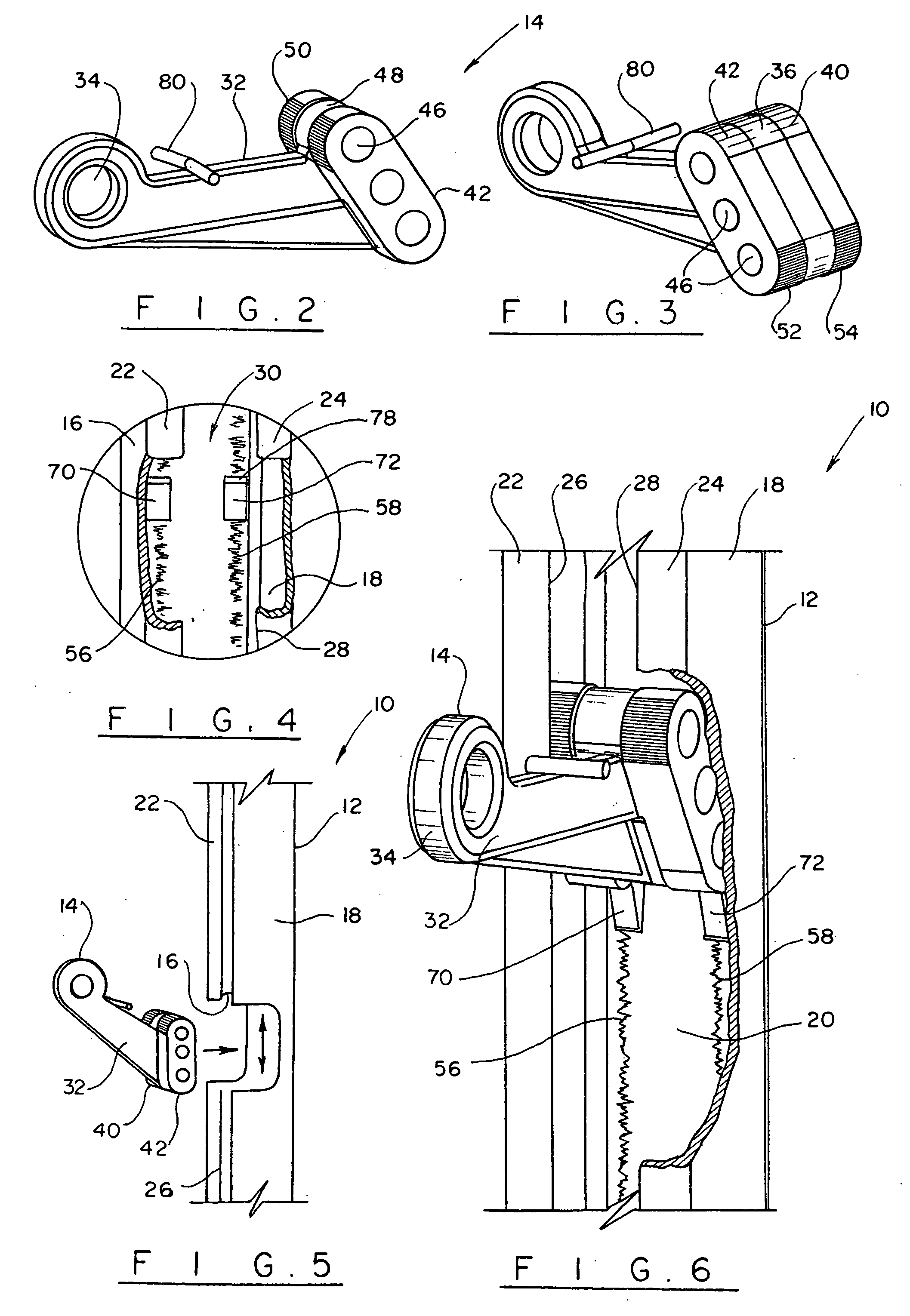
[0019]Turning now to the drawings in more detail, numeral 10 designates the safety apparatus of the present invention. The apparatus 10 comprises an elongated track member 12 and a slide body 14, which is adapted for sliding movement within the track member 12. The track member 12 comprises two parallel sides 16, 18 and a transverse joining web 20. The sides 16 and 18 each have inwardly facing edge portions 22, 24, respectively, which face inward in opposite directions to define a channel member of a generally C-shaped cross-section.

[0020]A gap 30 is formed between innermost edges 26, 28 of the edge portions 22, 24. The gap is large enough to allow extension of the arm of the slide body 14, while preventing disengagement of the sliding body 14 from the channel formed by the track member 12.

[0021]The slide body 14 comprises an arm 32 having a unitary formed eyelet 34 at a distal end portion and a cam section 36 at its proximate end portion. The eyelet 34 allows attachment of a safety...


PUM


Abstract

A safety accessory for use with a ladder to slow the speed of an accidental fall of a worker, who works in an elevated position. The accessory has a C-shaped track member and a slide body that moves inside the track member. The worker's harness is secured to the slide body. Contact surfaces of the track member and the slide member are serrated to slow the speed of an accidental fall. A plurality of locking wedge members is positioned in the channel formed by the track member to further decrease the speed of an accidental fall.

Description

BACKGROUND OF THE INVENTION[0001]The present invention relates to safety devices, and more particularly to safety devices that can be used with ladders or scaffolds in a variety of different environments.[0002]Government regulations, as well as general safety considerations require the use of a safety device, such as rope or harness whenever a worker works in elevated positions. Such devices are designed to be fastened to the worker via a safety waist belt or harness via a lanyard. The safety harness is then designed to be attached to a safety line, which in turn is attached to some elevated structure independently of the ladder or scaffold. In the event of a fall, the safety device is designed to slow the descent and / or lock the safety line in a position above ground to thereby prevent injury to the worker.[0003]Conventional safety harnesses have suffered from numerous disadvantages. For example, it is believed that prior art harnesses have been difficult and time consuming for a p...

Claims


Application Information

Patent Timeline
IPC IPC(8): E06C7/18
CPCE06C7/187
Inventor VOLLENWEIDER, EDGAR G.CAMPESI, MICHAEL
Owner M A CAMPESI FAMILY HLDG
Why Eureka
Try Eureka