Fixed support for parts in machine tools

Inactive Publication Date: 2010-02-25
AIRBUS OPERATIONS (SAS)
View PDF8 Cites 2 Cited by
  • Summary
  • Abstract
  • Description
  • Claims
  • Application Information

AI Technical Summary

Benefits of technology

[0016]Preferably, in order to prevent objects or tools from falling during machining ope

Problems solved by technology

However, the complexity involved in moving the machining heads with the precision required by the machined workpieces results in a ga

Method used


Image

  • Fixed support for parts in machine tools
  • Fixed support for parts in machine tools
  • Fixed support for parts in machine tools

Examples


Embodiment Construction

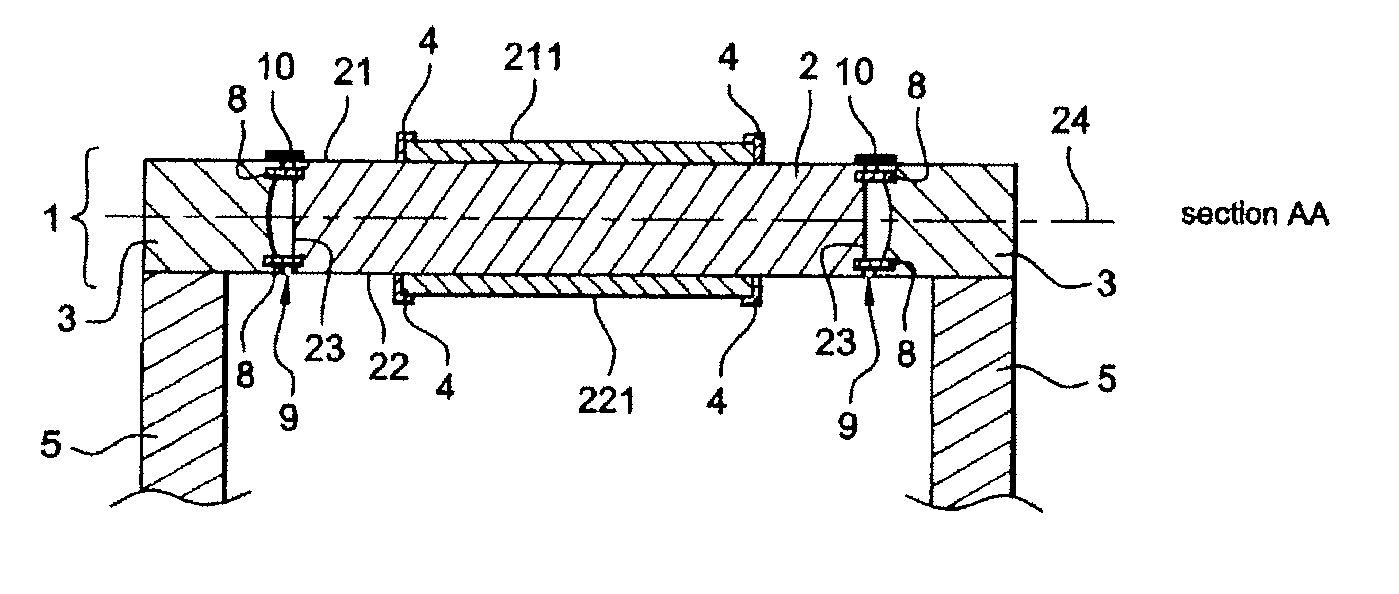
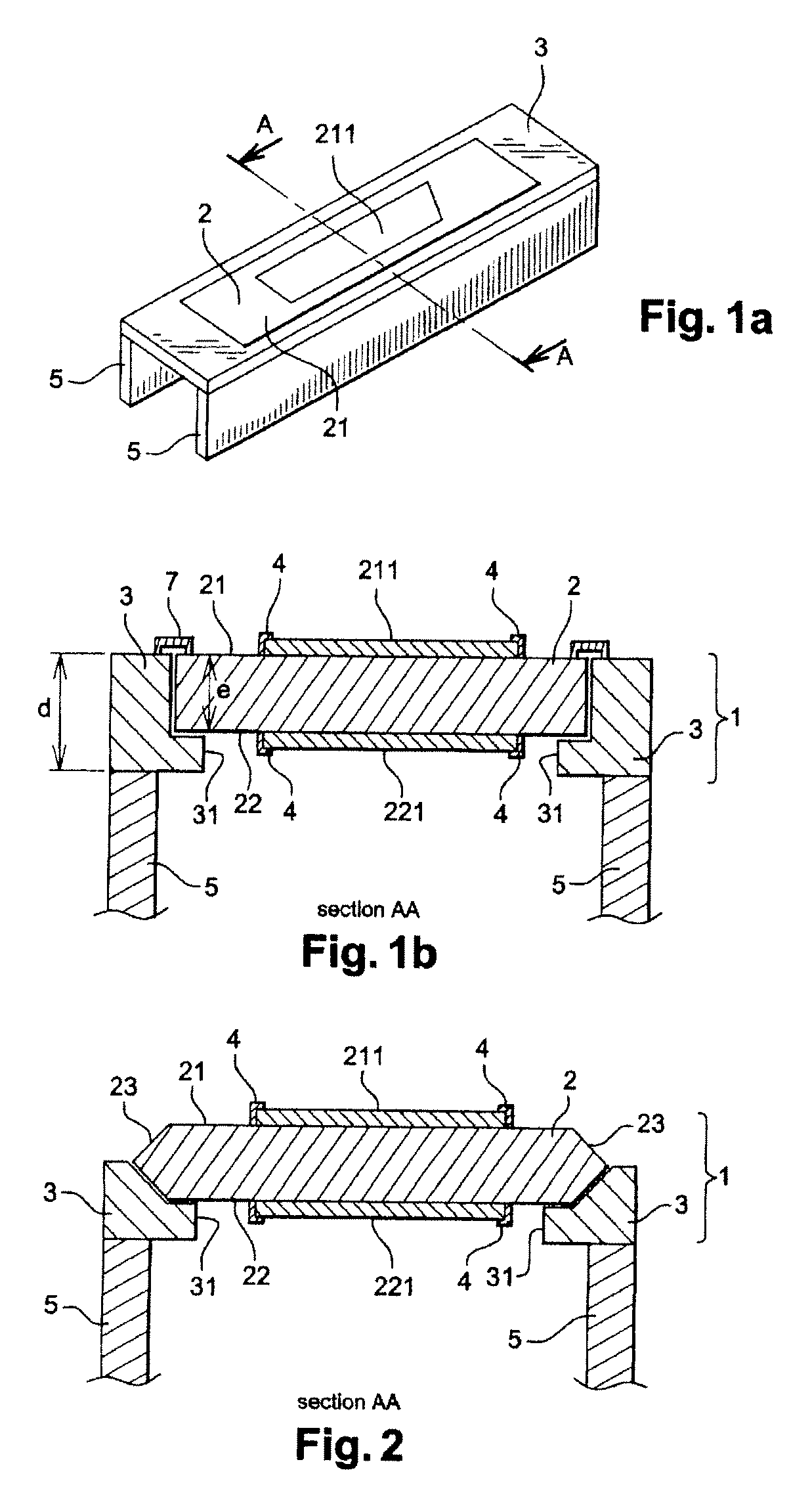
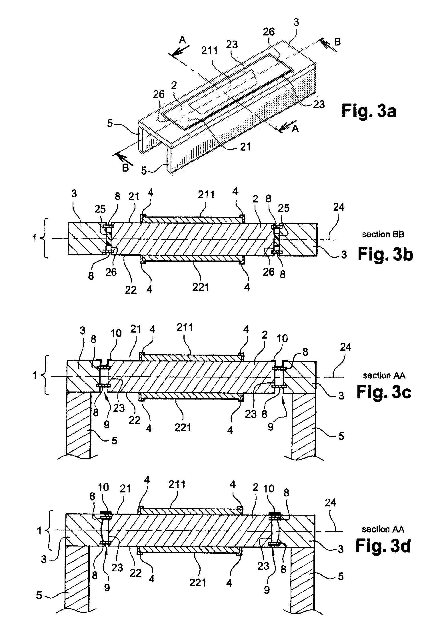
[0025]According to the aspects of the disclosed embodiments, a fixed workpiece support 1 for machine tools, as illustrated in FIGS. 1a, 1b, comprises a table frame 3 and a table 2 having:[0026]a first face 21 capable of holding a workpiece 211 to be machined in a fixed position,[0027]a second, upper, face 22, opposed and substantially parallel to said first face 21, capable of holding a workpiece 221 to be machined in a fixed position.

[0028]The support 1 is substantially horizontal, and the table 2 has a length at least equal to the length of the largest workpiece to be machined.

[0029]The support 1 has sufficient rigidity to ensure that the table is stable when workpieces are being machined.

[0030]To ensure that the workpiece to be machined is held on the table with sufficient rigidity, retaining means 4, such as, for example, flanges, are arranged in a conventional manner on each of the faces 21, 22 of the table 2.

[0031]During the machining operations, the table 2 is held on the tab...


PUM


Abstract

A fixed carrier for machine tool parts includes a table frame and a table having a first face That can hold a first part to be machined, the first face being fixed above a machining device and the first part being stationary during the machining process. The table also has a second face for holding steady a second part to be machined.

Description


Claims


Application Information

Patent Timeline
Owner AIRBUS OPERATIONS (SAS)
Why Eureka
Try Eureka