Power Factor Correction in and Dimming of Solid State Lighting Devices

a technology of power factor correction and lighting device, which is applied in the direction of electric variable regulation, process and machine control, instruments, etc., can solve the problems of corresponding increase in the cost of led driver circuitry, relatively small leds, and long operating li

Active Publication Date: 2010-02-25
MAXIM INTEGRATED PROD INC
View PDF7 Cites 51 Cited by
  • Summary
  • Abstract
  • Description
  • Claims
  • Application Information

AI Technical Summary

Benefits of technology

[0014]In one embodiment, the control circuit is configured to enable the LED driver to provide a switching or altering current to the LED array. In this embodiment, a substantially small capacitor is connected across the LED array load. Because the large capacitance required by the two-stage prior art approach is eliminated,

Problems solved by technology

When compared to halogen lamps, LEDs are relatively smaller, and have a longer operating life.
These disadvantages include the use of higher number of total components to drive the LED driver, and a corresponding increase in cost of the LED driver circuitry.
This approach also includes operational inefficiencies, as it requires the input AC source to be converted to DC before applications to the array of LEDs.
Prior art approaches also require the LED current to be measured and monitored in order to achieve PFC, further contributing to the operational inefficiency.

Method used


Image

  • Power Factor Correction in and Dimming of Solid State Lighting Devices
  • Power Factor Correction in and Dimming of Solid State Lighting Devices
  • Power Factor Correction in and Dimming of Solid State Lighting Devices

Examples


Embodiment Construction

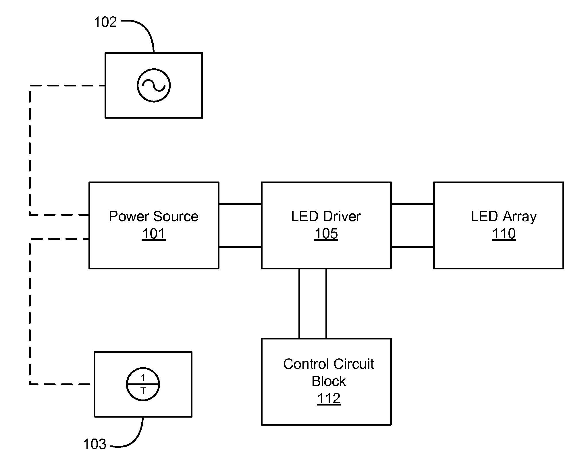
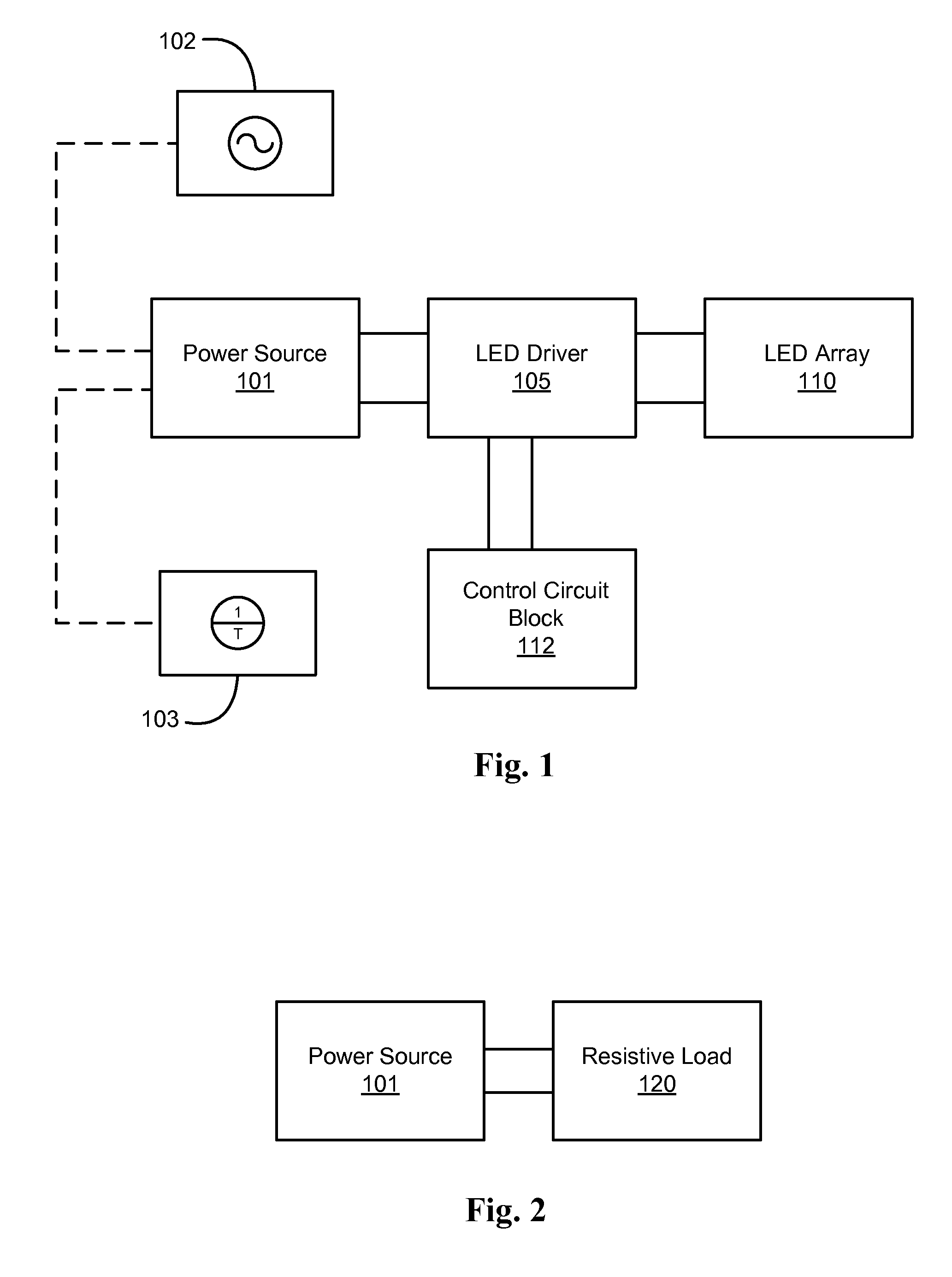
[0030]In the following description, for the purpose of explanation, specific details are set forth in order to provide an understanding of the invention. It will be apparent, however, to one skilled in the art that the invention may be practiced without selected of these details. One skilled in the art will recognize that embodiments of the present invention, some of which are described below, may advantageously be incorporated into a number of different devices and systems. Structures and devices shown in block diagram are illustrative of exemplary embodiments of the invention and are included to avoid obscuring the invention. Furthermore, connections between components within the figures are not intended to be limited to direct connections. Rather, such connections between components may be modified, reconfigured, or otherwise changed by intermediary components.

[0031]Reference herein to “one embodiment” or “an embodiment” of the invention means that a particular feature, structure...


PUM


Abstract

An apparatus and method provides a driver circuit that provides for power factor correction (PFC) to a load, such as a solid-state lighting (SSL) device, such as, for example, a light emitting diode (LED) or an array or cluster of LEDs. A programmable reference is provided in the circuit to operate in a fixed frequency peak current mode control (FFPCMC) or in a fixed frequency average current mode control (FFACMC). A driver circuit is employed to operate the SSL device using power derived from a main power source which may be DC or AC. In a FFPCMC embodiment, a programmable power reference is programmed to be a fixed DC voltage. In a FFACMC embodiment, source input current to the circuit can be programmed to be proportional to the rectified AC voltage after a bridge rectifier.

Description

CROSS REFERENCE TO RELATED PATENT APPLICATIONS[0001]This application claims priority to U.S. Provisional Application Ser. No. 61 / 091,715, entitled “POWER FACTOR CORRECTION IN SOLID STATE LIGHTING DEVICES”, filed Aug. 25, 2008, and U.S. Provisional Application Ser. No. 61 / 161,724, entitled “LED DRIVER COMPATIBLE WITH AN ELECTRONIC TRANSFORMER”, filed on Mar. 19, 2009, both provisional applications which are incorporated herein in their entirety by their reference.BACKGROUND[0002]1. Field of the Invention[0003]The present invention relates to a control system for controlling currents in an electronic system. More particularly, the present invention relates to a control system for controlling the current in drivers for solid-state lighting (SSL) devices, such as, for example, a light emitting diode (LED) or an array or cluster of light emitting diodes (LEDs) having driver circuitry that is compatible with electronic transformers and supports dimming functionality. It also applies to so...

Claims


Application Information

Patent Timeline
Patent Type & Authority Applications(United States)
IPC IPC(8): H05B41/36H05B44/00
CPCH05B33/0815Y02B20/383H05B33/0845Y02B20/348H05B45/10Y02B20/30H05B45/38H05B45/382H05B45/3725H05B45/60
Inventor HARIHARAN, SURESH
Owner MAXIM INTEGRATED PROD INC
Why Eureka
Try Eureka