Metallized film capacitor

a technology of metallized film capacitors and capacitors, which is applied in the direction of wound capacitors, fixed capacitor details, fixed capacitors, etc., can solve the problems of increasing product cost, occupying a large space, and affecting the use of aluminum electrolytic capacitors on dc 500 v

Active Publication Date: 2006-08-15
PANASONIC CORP
View PDF13 Cites 46 Cited by
  • Summary
  • Abstract
  • Description
  • Claims
  • Application Information

AI Technical Summary

Benefits of technology

[0013]To solve the problems mentioned above, the present invention aims at providing a metallized film capacitor with a compact size, a large capacitance, a low inductance and a reduced number of parts.

Problems solved by technology

Contrarily the aluminum electrolytic capacitor is difficult for use on DC 500 V or higher due to restrictions of the withstand voltage of the dielectric oxide film.
The metallized film capacitor has been widely used for high voltage of DC 500 V or higher, even in a case of DC circuit, because the aluminum electrolytic capacitor is difficult to use on a high voltage application as mentioned above.
However, a plurality of single metallized film capacitors connected in parallel occupies a large space.
Additional problem is that many bus-bars are necessary for connection, causing an increase in product cost.
Another problem is that electrical connection using many bus-bars causes a long wiring length, resulting in a large total inductance.
This will cause eventually a deterioration of evaporated metals on the film and will decrease the capacitance greatly with time.

Method used


Image

  • Metallized film capacitor
  • Metallized film capacitor
  • Metallized film capacitor

Examples


exemplary embodiment 1

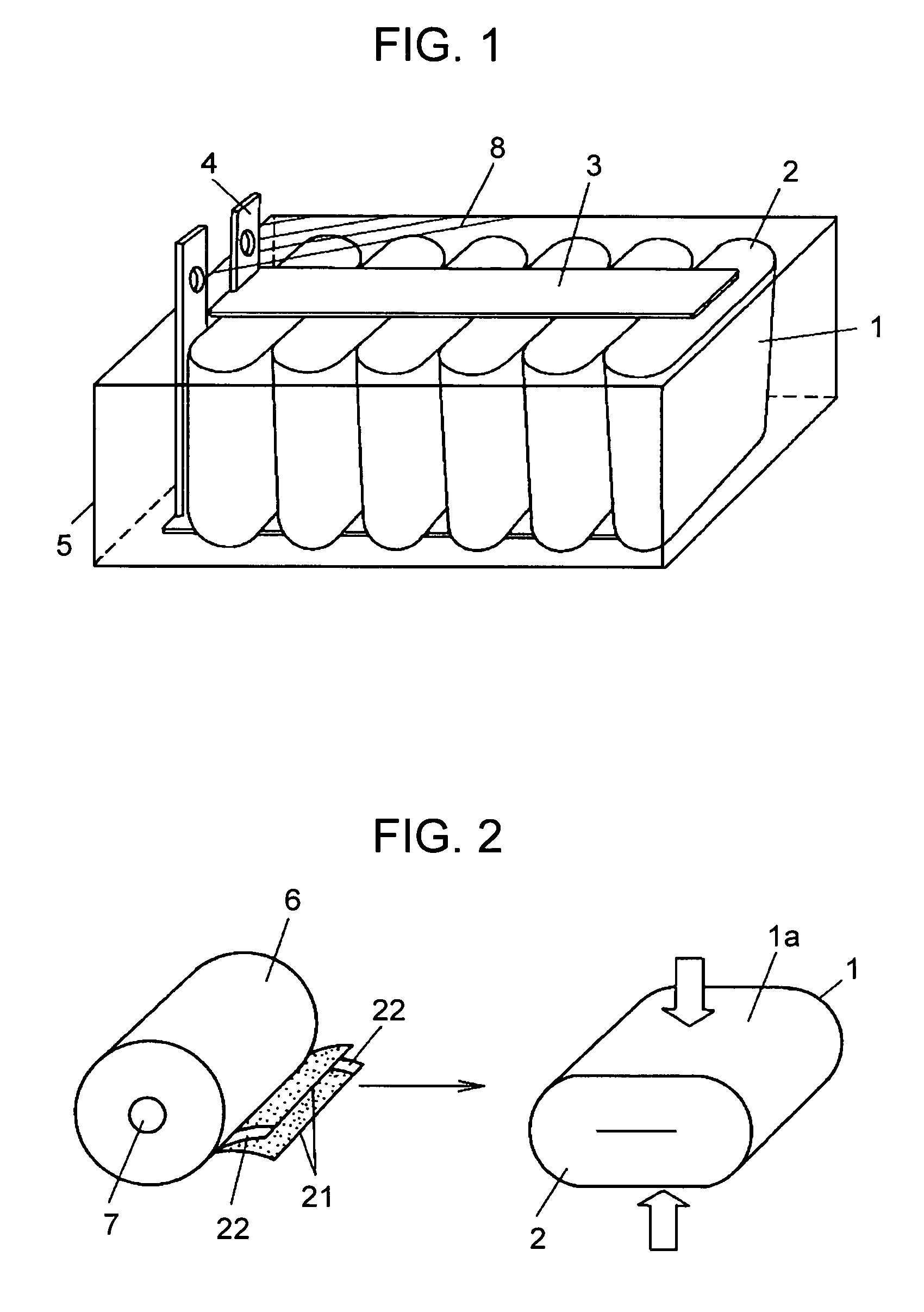
[0029]Capacitor 1 is formed of two sheets of metallized film 21, evaporated on one side, rolled up and flattened using a polypropylene film as the dielectric as shown in FIG. 2. Metallized film 21 of capacitor 1 is provided with metallized contact electrodes formed by zinc spraying on both ends in the width direction. A pair of elongated copper bus-bars 3, electrical conductors, connect each metallized contact electrode 2 of a plurality of capacitors 1 on both ends. Bending the ends of bus-bars 3 provides electrode terminals 4 for external connection. That is, electrode terminals 4 are integrated with bus-bars 3.

[0030]Capacitor case (case) 5 is formed from polyphenylene-sulfide (PPS). Instead of plastics such as PPS or polybutylene terephthalate (PBT), metals such as aluminum can be available for the case material. A plurality of capacitors 1 are aligned in case 5, appressed against flattened surfaces la toward a same direction, as shown in FIG. 1. Being positioned each metallized c...

exemplary embodiment 2

[0038]The metallized film capacitor used in exemplary embodiment 2 is mainly described on the points different from exemplary embodiment 1, as the basic configuration and functional effects of the metallized film capacitor are similar to those of exemplary embodiment 1, therefore similar elements have the same reference marks and detailed descriptions are omitted.

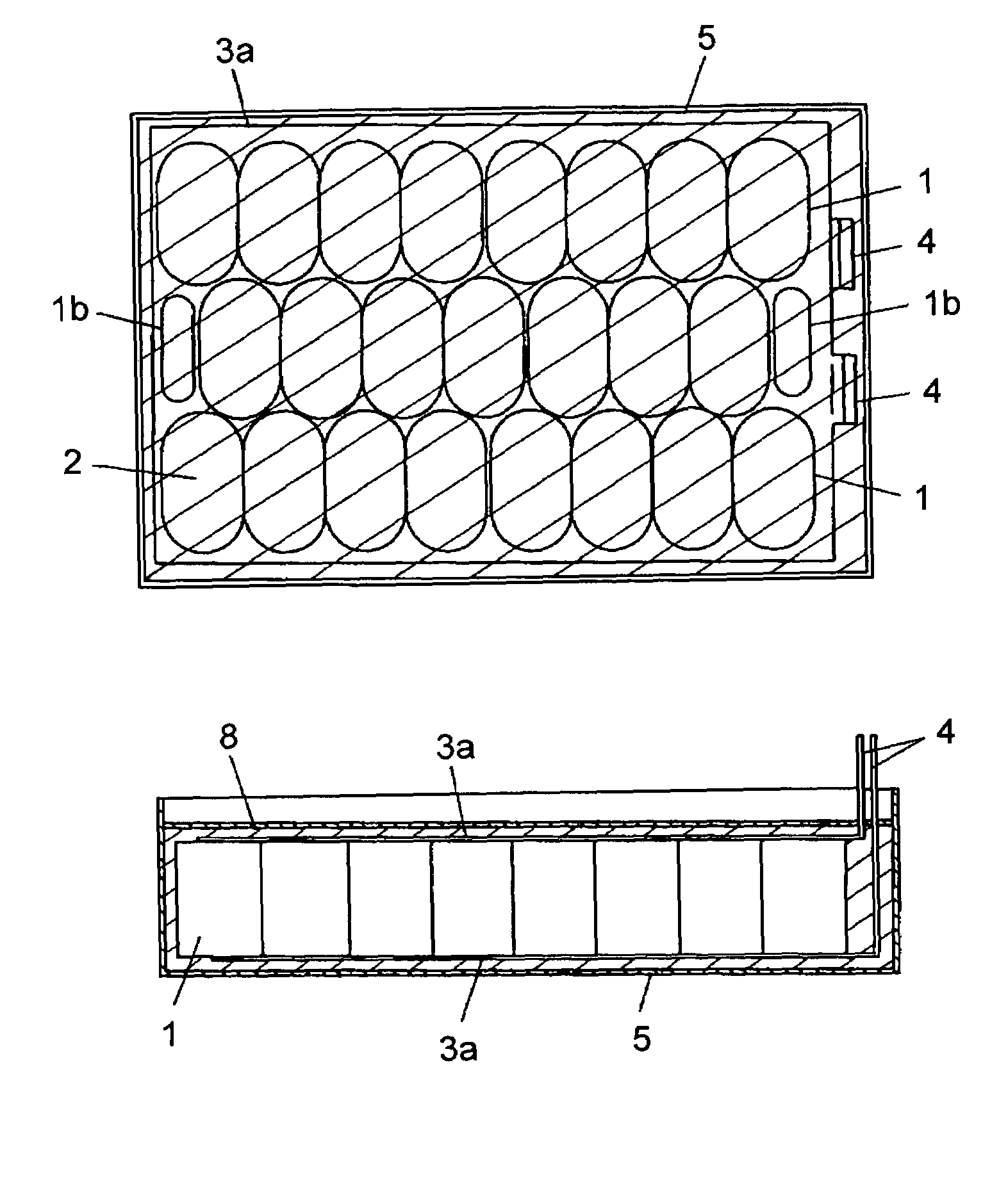
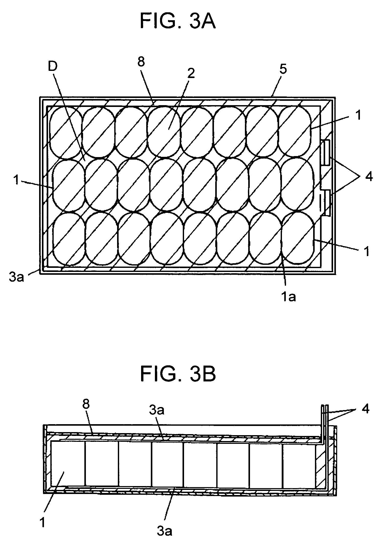
[0039]The size of case 5 is 160 mm wide, 120 mm long, and 75 mm high, and bus-bar 3a to connect metallized contact electrodes 2 has a plate-like size so as to cover the opening of case 5 as shown in FIGS. 3A and 3B. Moreover, case 5 is designed to include 24 pieces of capacitor elements 1 in case 5 by changing rolling numbers of metallized films 21 and the diameter of roll core 7. Twenty-four pieces of capacitor elements 1 are housed in case 5 arranged in a plurality of lines along with a certain direction. The single flattened capacitor element 1 has a capacitance of 58.3 μF, resulting a large amount of capacitance of 1400...

exemplary embodiment 3

[0040]The metallized film capacitor used in exemplary embodiment 3 is mainly described on the points different from exemplary embodiment 1, as the basic configuration and functional effects of the metallized film capacitor are similar to those of exemplary embodiment 1, therefore similar elements have the same reference marks and detailed descriptions are omitted.

[0041]Exemplary embodiment 3 employs capacitor case (case) 1a having taller side surface in left-hand half than in right-hand half, an uneven side view, as shown in FIG. 4B that is a modification of the case used in exemplary embodiment 2.

[0042]The flattened capacitor element 1 has two kinds of capacitor element having different widths of the metallized film. The taller left-hand half of case 5a houses taller capacitor elements 1 formed of wider metallized films 21. The lower right-hand half of case 5a houses lower capacitor elements 1 formed of narrower metallized films 21. Every capacitor element 1 is housed in case 5a, p...


PUM


Abstract

The present invention is to provide a metallized film capacitor having a compact size, a large capacitance and a low inductance whereas number of parts is reduced. The metallized film capacitor comprises: a plurality of capacitor elements (1) provided with metallized contact electrodes (2) on both ends in the width direction; a bus-bar (3) to connect each of a plurality of electrodes (2) on one end; and a capacitor case (5) to house a plurality of capacitor elements (1), wherein a plurality of capacitor elements (1) are arranged in the capacitor case such that one side of electrodes (2) faces the opening surface of capacitor case (1) and each electrode (2) of one of both ends of each capacitor element (1) are positioned generally coplanarly.

Description

[0001]This application is a U.S. National Phase Application of PCT / JP2003 / 015465.[0002]1. Technical Field[0003]The present invention relates to a metallized film capacitor used for electronic, electrical and industrial equipment, vehicles or the like and particularly to a smoothing capacitor for use in an inverter circuit for motor starting installed in hybrid vehicles or the like.[0004]2. Background Art[0005]The metallized film capacitor, although having a disadvantage of large volume compared with the aluminum electrolytic capacitor of an equivalent amount of capacitance, has excellent properties of low losses, high withstand voltage, low temperature and frequency dependency or the like. Particularly the film capacitor can work well under high voltages of DC 500 V or higher if the film thickness is controlled suitably due to a high withstand voltage of the dielectric film.[0006]Contrarily the aluminum electrolytic capacitor is difficult for use on DC 500 V or higher due to restric...

Claims


Application Information

Patent Timeline
Patent Type & Authority Patents(United States)
IPC IPC(8): H01G4/32H01G4/08H01G4/228H01G2/10H01G4/38H01L29/00
CPCH01G2/10H01G4/38H01G4/228Y02T10/7022Y02T10/70
Inventor SAITO, TOSHIHARUSHIOTA, KOHEITAKEOKA, HIROKI
Owner PANASONIC CORP
Why Eureka
Try Eureka