

Integrated air conditioner
- Summary
- Abstract
- Description
- Claims
- Application Information
AI Technical Summary
Benefits of technology
Problems solved by technology
Method used
Image

Examples
first embodiment
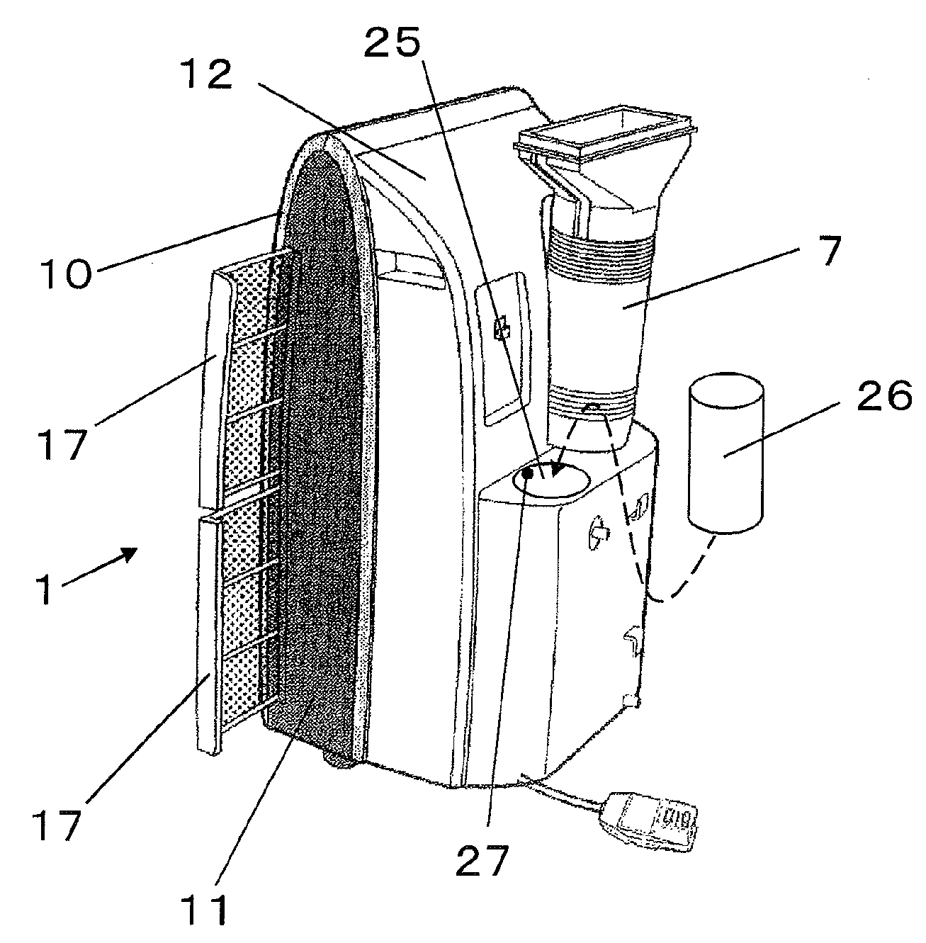
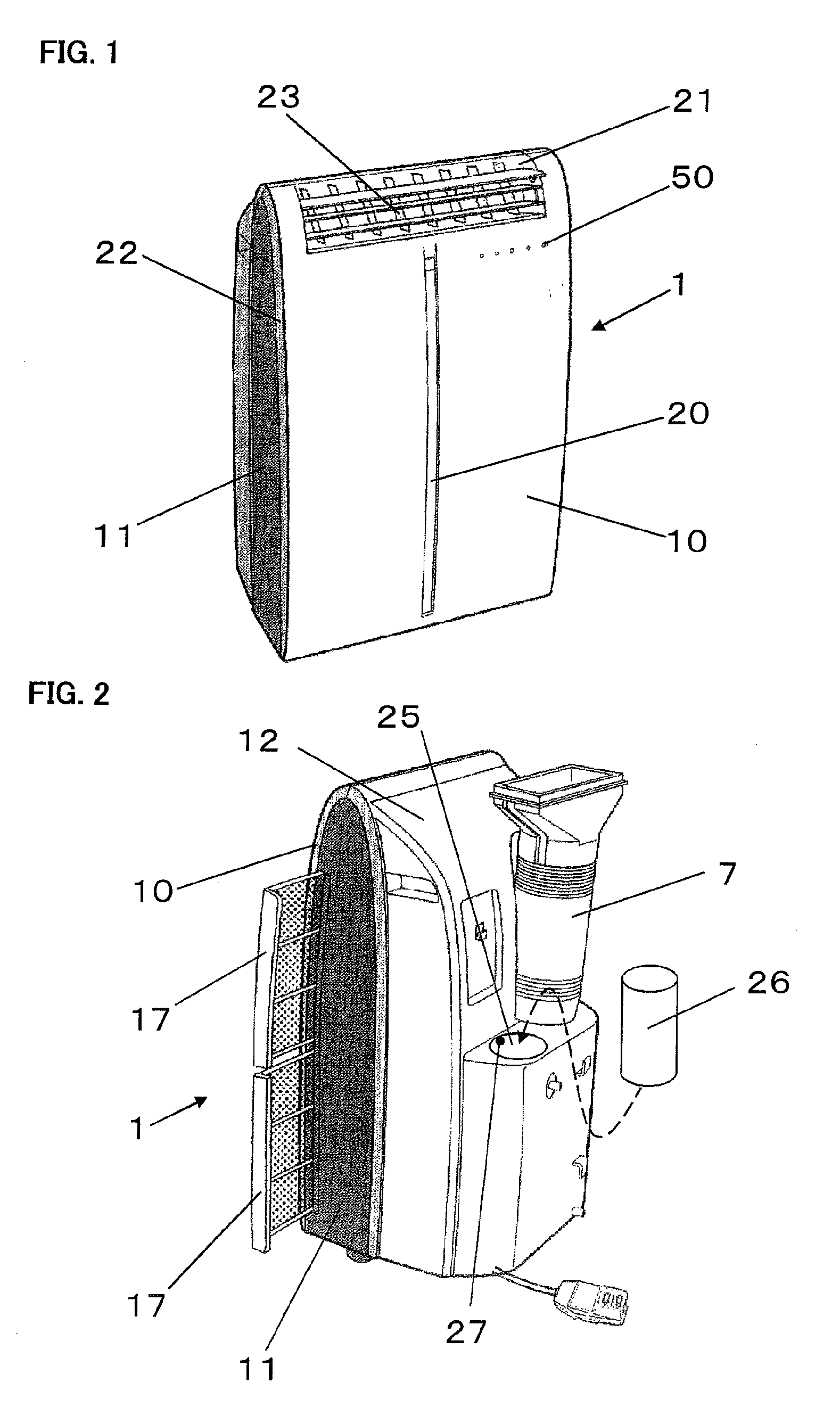
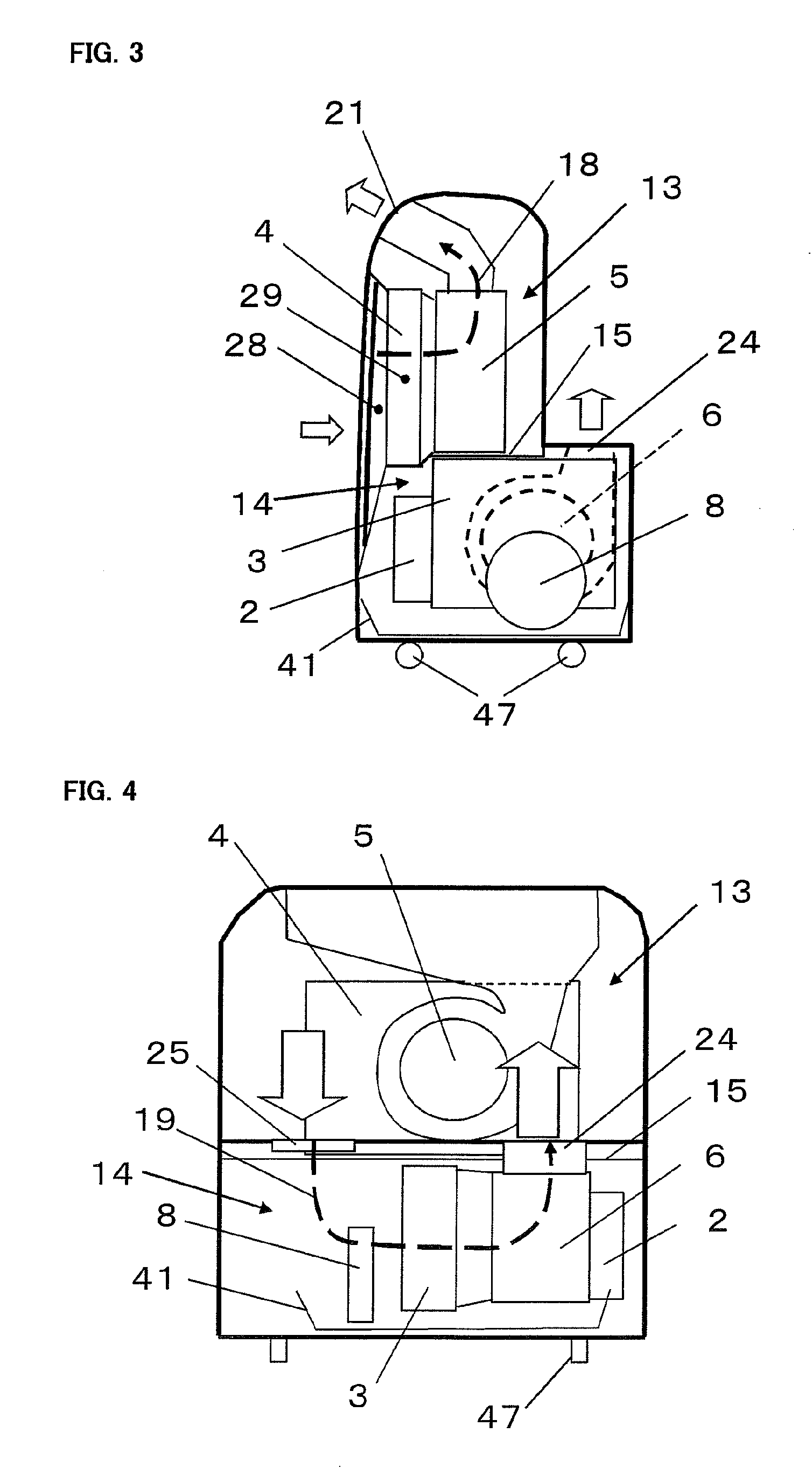
[0038]A first embodiment of the present invention will be described with reference to the drawings. An integrated air conditioner according to the present invention has, as shown in FIGS. 1 to 4, a compressor 2, a condenser 3, an evaporator 4 and a restriction mechanism (not shown) housed in a cabinet 1. A refrigerating cycle is formed by these components. The air conditioner performs a cooling operation for cooling the interior of a room by producing cool wind. Accordingly, the air conditioner has a blow fan 5 on the evaporator 4, an exhaust fan 6 on the condenser 3, a drain pan 41 in which drain water produced by cooling operation is collected, and a splasher 8 provided as a water feed device for leading water collected in the drain pan 41 to the condenser 3.
[0039]The cabinet 1 has a surrounding structure formed of a front panel 10, a left-right pair of side plates 11 and a back plate 12, as shown in FIGS. 1 and 2. The cabinet 1 is sectioned into an upper cooling chamber 12 and a ...
second embodiment
[0068]A second embodiment of the present invention will be described with reference to FIG. 7. A feature of the second embodiment resides in that when supply / expelling of air in the heat release chamber by the double-duct system, the control section detects the difference between the temperature of the evaporator and the indoor temperature measured with temperature sensors and stops the operation of the splasher 8 provided as a water feed device when the temperature difference becomes larger than a predetermined value. In other respects, the structure of the second embodiment is the same as that of the first embodiment.
[0069]More specifically, in the vent passage 18 of the cooling chamber 13 of the air conditioner, a temperature sensor 28 for measuring the temperature of air drawn in is provided between the filter 17 and the evaporator 4, and a temperature sensor 29 for measuring the temperature of the surface of the evaporator 4 is also provided. Detection signals from the temperat...
third embodiment
[0072]A third embodiment of the present invention will be described with reference to FIGS. 8 and 9. A feature of the third embodiment resides in that the exhaust duct 7 is off the exhaust port 24 in a normal state; the exhaust duct 7 is fitted to the exhaust port 24 as required; and an exhaust duct fitting detection section for detecting the completion of fitting of the exhaust duct 7 to the exhaust port 24 is provided to enable discrimination of the double-duct system and the single-duct system in the control section. In other respects, the structure of the third embodiment is the same as that of the second embodiment.
[0073]More specifically, as shown in FIG. 8, the exhaust duct 7 is off the exhaust port 24, and an exhaust duct fitting detection section 30 for detecting the completion of fitting of the exhaust duct 7 to the exhaust port 24 is provided on the exhaust port 24. The exhaust duct fitting detection section 30 is constituted by a microswitch, which is turned on to output...
PUM
 Abstract
Description
Claims
Application Information