Light emitting element driving apparatus

a technology of light emitting elements and driving apparatuses, which is applied in the direction of electric variable regulation, process and machine control, instruments, etc., can solve the problems of reducing the accuracy of the current driving the light emitting element group, and affecting the operation of the driving apparatus. , to achieve the effect of reducing power consumption, preventing voltage breakdown, and enhancing the responsiveness of the current driving circui

Inactive Publication Date: 2010-03-04
PANASONIC CORP
View PDF6 Cites 12 Cited by
  • Summary
  • Abstract
  • Description
  • Claims
  • Application Information

AI Technical Summary

Benefits of technology

[0016]In consideration of the problems encountered in the above-mentioned conventional light emitting element driving apparatus, an object of the present invention is to provide a light emitting element driving apparatus capable of supplying a stable power source voltage during duty control. Another object of the present invention is to provide a light emitting element driving apparatus characterized in that current driving circuits contained therein have a high withstand voltage and that circuits connected in parallel with the current driving circuits are prevented from withstand voltage breakdown.
[0019]In the light emitting element driving apparatus according to the present invention, in the OFF state of the light emitting elements (all the current driving circuits are in the OFF state), since the adjustment operation of the power source circuit is continued using the auxiliary feedback circuit, the power source voltage is stabilized to a predetermined voltage even in the light emitting element OFF state. Hence, in both the light emitting element OFF state and the light emitting element ON state (one or more current driving circuits are in the ON state), even if the period of the light emitting element OFF state becomes long, the width of fluctuations including ripples and the like in the power source voltage V69 can be made sufficiently small. As a result, since the current sources operable to generate the drive currents in the current driving circuits can maintain a voltage sufficient to perform current driving at all times, when the light emitting element OFF state is switched to the light emitting element ON state, the responsiveness of the current driving circuits can be enhanced. Furthermore, since the power source voltage is prevented from rising excessively in the light emitting element OFF state, withstand voltage breakdown is prevented, power consumption is reduced, and EMI is also reduced in the light emitting element driving apparatus. As described above, the light emitting element driving apparatus can perform accurate duty control using the auxiliary feedback circuit.
[0020]Furthermore, with the light emitting element driving apparatus according to the present invention, the current driving circuits are each formed of an N-channel MOS transistor and a current source. Hence, by using components having a high withstand voltage as the N-channel MOS transistors and by using components having a low withstand voltage in the circuits connected in parallel between the feedback output terminals and the ground, such as the current sources, the main feedback circuit, the auxiliary feedback circuit, and the input setting circuit, both the high-voltage driving of the light emitting element groups and the use of the low withstand voltage components can be achieved. By using components having a high withstand voltage, the numbers of the light emitting element groups, the N-channel MOS transistors, the current sources, etc. can be reduced. As a result, the power consumption of the light emitting element driving apparatus can be reduced, and the cost thereof can also be reduced. Moreover, by using components having a low withstand voltage, the areas of the semiconductor chips for the circuits are decreased. As a result, the power consumption of the light emitting element driving apparatus can be reduced, and the cost thereof can also be reduced.

Problems solved by technology

However, the conventional light emitting element driving apparatus has problems described below.
Hence, accurate duty control cannot be performed.
Moreover, in addition to the above-mentioned problems, there are problems in which since the above-mentioned feedback loop is substantially cut when all the current driving circuits 101A, 101B and 101C are in the OFF state, ripples are generated in the power source voltage of the power source circuit 107, whereby the accuracy of the currents for driving the light emitting element groups is degraded and EMI (electro-magnetic interference) increases.

Method used


Image

  • Light emitting element driving apparatus
  • Light emitting element driving apparatus
  • Light emitting element driving apparatus

Examples


first embodiment

1. First Embodiment

1.1 Configuration and Operation

1.1.1 General Description

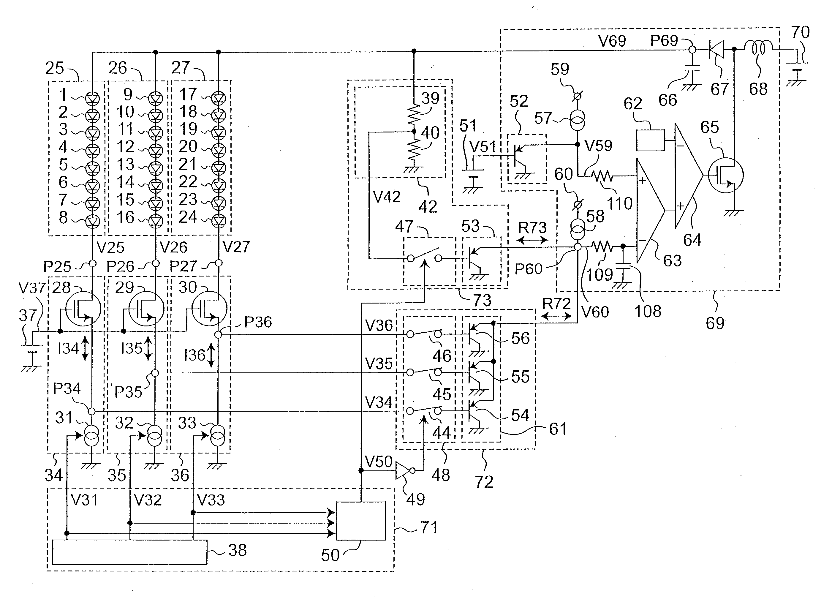
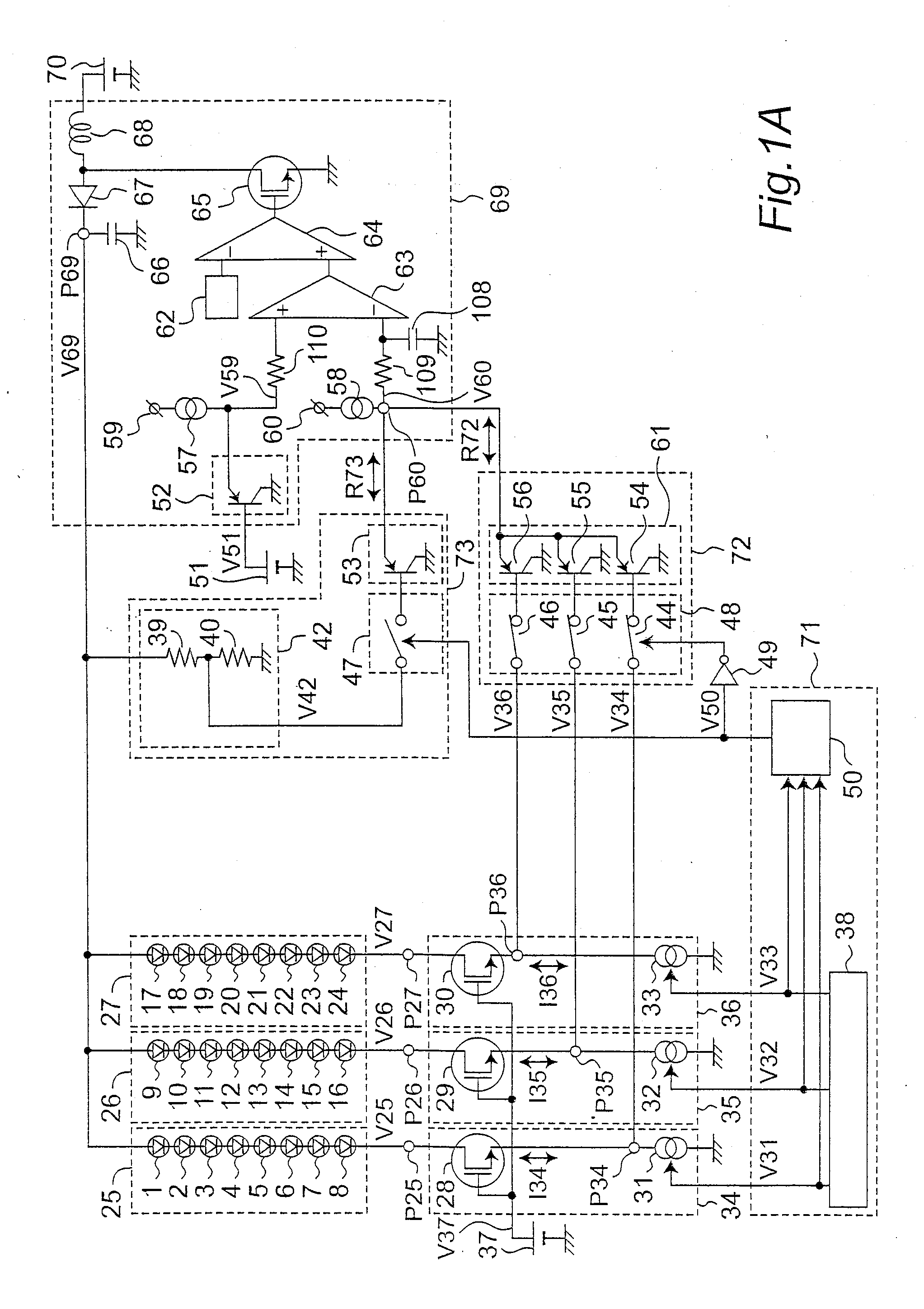
[0029]FIG. 1A is a circuit diagram showing a configuration of a light emitting element driving apparatus according to a first embodiment. In FIG. 1A, the light emitting element driving apparatus according to the first embodiment contains a light emitting element group 25, a light emitting element group 26, a light emitting element group 27, a current driving circuit 34, a current driving circuit 35, a current driving circuit 36, a voltage source 37, a voltage source 51, a voltage source 70 (also referred to as a DC power source or a DC voltage source), a control circuit 71, a main feedback circuit 72, an auxiliary feedback circuit 73, an inverter 49, and a power source circuit 69.

[0030]The light emitting element group 25 contains a light emitting element 1, a light emitting element 2, a light emitting element 3, a light emitting element 4, a light emitting element 5, a light emitting element 6, a light emitti...

modification example

1.4 Modification Example

[0094]In the light emitting element OFF state, the drive currents I34 to I36 may be 0 mA as in the above-mentioned specific example or may have a current value slightly larger than 0 mA. Even in the case that the drive currents I34 to I36 are slightly larger than 0 mA, the drive currents I34 to I36 are set to a current value obviously smaller than that obtained in the light emitting element ON state. There is a possibility that the operations of the current driving circuits 34 to 36 are stabilized by setting the drive currents I34 to I36 to a value slightly larger than 0 mA.

[0095]The power source circuit 69 may be a step-down power source circuit that generates the power source voltage V69 smaller than the DC voltage generated from the voltage source 70.

[0096]The state signal generating circuit 50 may independently control the switches 44, 45 and 46 of the switching circuit 48. In this case, the state signal generating circuit 50 sets the switch 44 to the ON ...

second embodiment

2. Second Embodiment

[0102]In the following description of a second embodiment, differences from the first embodiment will be mainly described. Since the configurations, operations and effects other than those relating to the differences are similar to those according to the first embodiment, their descriptions are omitted.

[0103]In the description of the second embodiment, a configuration in which at least one of the switching circuit 47 and the switching circuit 48 is omitted will be described.

[0104]FIG. 2 is a circuit diagram showing a configuration of a light emitting element driving apparatus according to the second embodiment. The configuration of the second embodiment shown in FIG. 2 is different from the configuration of the first embodiment shown in FIG. 1A in that the switching circuit 48, the switching circuit 47, the inverter 49 and the state signal generating circuit 50 are omitted. The auxiliary feedback voltage generating circuit 42 is connected to the input setting cir...


PUM


Abstract

The N light emitting element groups each include one or more light emitting elements. The power source circuit includes a control input terminal and supplies the power source voltage to the N light emitting element groups. The N current driving circuits, each including a feedback output terminal, generate N drive currents for driving the respective N light emitting element groups and generate main feedback voltages at the feedback output terminals based on the power source voltage. The main feedback circuit applies a main feedback signal to the control input terminal based on the N main feedback voltages. The auxiliary feedback circuit applies an auxiliary feedback signal to the control input terminal based on the power source voltage. The power source circuit adjusts the power source voltage based on at least one of the main feedback signal and the auxiliary feedback signal.

Description

BACKGROUND OF THE INVENTION[0001]1. Field of Invention[0002]The present invention relates to a driving apparatus for driving light emitting elements, and more particularly, to a light emitting element driving apparatus for driving light emitting elements, such as LEDs (light emitting diodes), by using a DC / DC converter as a voltage source.[0003]2. Description of Related Art[0004]As a conventional light emitting element driving apparatus, a configuration shown in FIG. 6 has been proposed to reduce power loss and enhance efficiency (for example, refer to Japanese Laid-open Patent Publication No. 2007-242477).[0005]In FIG. 6, current driving circuits 101A, 101B and 101C current-drive light emitting element groups 100A, 100B and 100C, respectively. Each of the light emitting element groups 100A, 100B and 100C contains multiple LEDs, and the multiple LEDs are connected in series so that a drive current flows in the forward direction from the anode to the cathode thereof. Furthermore, vol...

Claims


Application Information

Patent Timeline
Patent Type & Authority Applications(United States)
IPC IPC(8): H05B37/02
CPCH05B33/0815H05B33/0827H05B33/0818G09G3/342G09G2320/064G09G2330/04G09G2330/08H05B45/375H05B45/38H05B45/46
Inventor KATAOKA, SHINICHIROUEDA, RYUJITAKATA, GOITOU, DAISUKEYAMAMOTO, YASUNORIKAWAHARA, TSUKASA
Owner PANASONIC CORP
Why Eureka
Try Eureka