
Image processing apparatus, image processing method, and program for attaining image processing

Active Publication Date: 2010-03-04
138 EAST LCD ADVANCEMENTS LTD
View PDF12 Cites 29 Cited by
  • Summary
  • Abstract
  • Description
  • Claims
  • Application Information

AI Technical Summary

Benefits of technology

[0023]a sixth step of detecting edge noise that is an erroneously determined edge direction by comparing the edge direction set in the edge direction map with the edge directions of surrounding pixels, and removing the edge noise; and
[0027]Since natural images exhibit significant spatial correlation, edge directions usually occur as blocks of the same edge direction. Consequently, applying the method described above makes it possible to effectively remove an edge noise included in the edge direction map.
[0031]It is not necessarily impossible for a correct edge direction to be mistakenly determined to be edge noise during edge noise removal. When such an erroneous determination occurs, removing the edge noise of the edge direction map may have the effect of introducing new edge noise. Therefore, rather than removing the edge noise for all areas of the edge direction map, edge noise is removed only for areas for which edge noise removal is actually necessary. The risk of introducing new edge noise can thereby be reduced. Specifically, in an area in which aliasing is unlikely to occur, since no problems occur even when edge noise is present, there is little need to remove the edge noise. Experimentation has shown that aliasing is unlikely to occur in areas in which there is significant variation between color components having the same mosaic image data, or in areas in which there is almost no variation. Consequently, adopting a configuration in which an area is extracted in which the amount of variation between color components having the same mosaic image data is smaller than a prescribed first threshold value and larger than a second threshold value (which is smaller than the first threshold value), and in which the edge noise is removed only for the extracted area, makes it possible to reduce the risk of introducing new edge noise into the edge direction map. Since there is no need to remove edge noise for all the areas of the edge direction map, the edge noise can be rapidly removed from the edge direction map.
[0040]a sixth function for detecting edge noise that is an erroneously determined edge direction by comparing the edge direction set in the edge direction map with the edge directions of surrounding pixels, and removing the edge noise; and
[0042]The computer reads the program according to this embodiment to attain the respective functions described above and adequately interpolate the missing color components of the mosaic image data. This arrangement thus facilitates the high-speed generation of the color image data while effectively preventing the occurrence of aliasing colors.

Problems solved by technology

This naturally consumes the time for interpolation and may cause the occurrence of aliasing colors due to interpolation error.
Consequently, when viewed in diagonal directions from the target pixel, even when the target pixel has different edge directions on both sides thereof, the edge direction of the target pixel cannot immediately be determined to be edge noise.
However, when the edge directions of the four pixels diagonally adjacent to the target pixel are all the same as each other, and the edge directions are different than the edge direction of the target pixel, it is highly probable that the edge direction of the target pixel is edge noise.
It is not necessarily impossible for a correct edge direction to be mistakenly determined to be edge noise during edge noise removal.
When such an erroneous determination occurs, removing the edge noise of the edge direction map may have the effect of introducing new edge noise.
For some characteristics of the edge noise, it may also be impossible for the edge noise to be completely removed by a single method.

Method used


Image

  • Image processing apparatus, image processing method, and program for attaining image processing
  • Image processing apparatus, image processing method, and program for attaining image processing
  • Image processing apparatus, image processing method, and program for attaining image processing

Examples


modification 1

[0078]H-1. Modification 1

[0079]H-2. Modification 2

modification 3

[0080]H-3. Modification 3

A. System Configuration

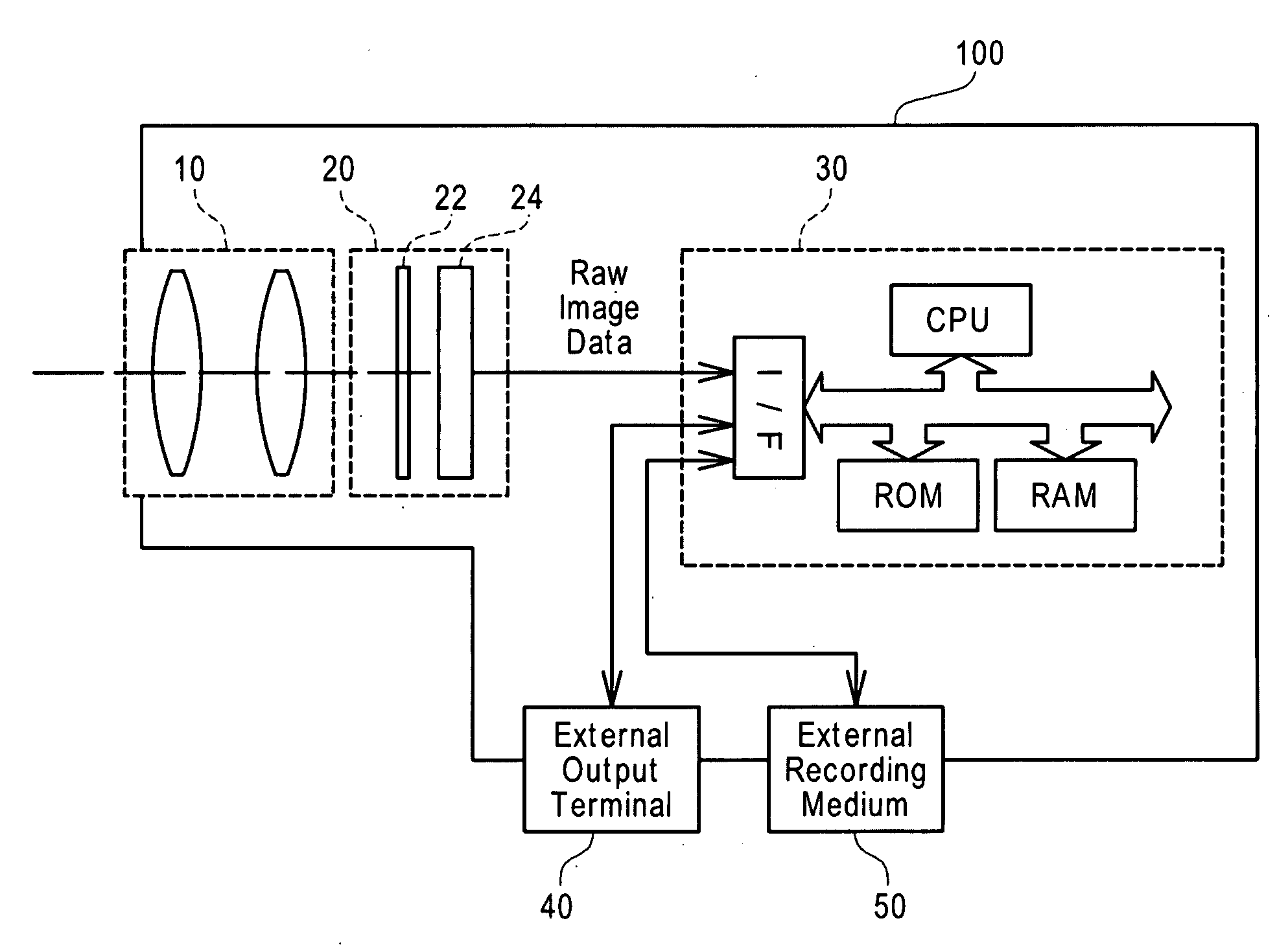
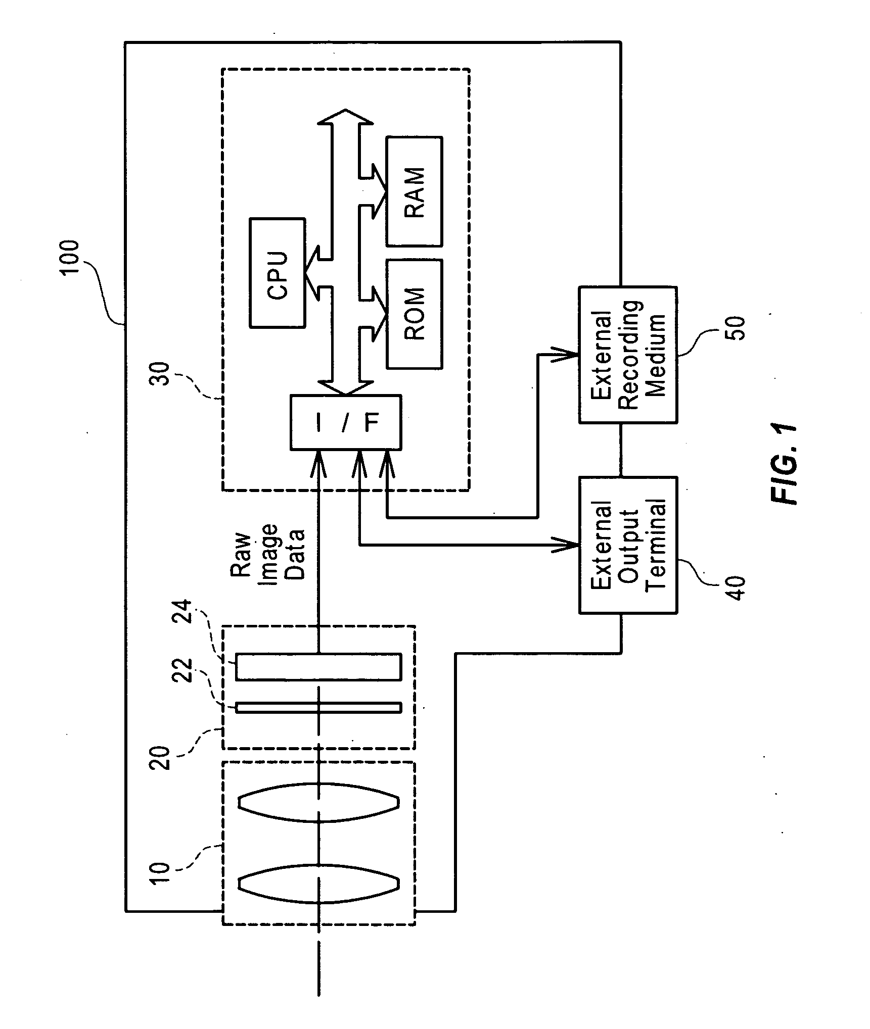
[0081]FIG. 1 schematically illustrates the configuration of a digital camera 100 equipped with an image processing apparatus 30 in one embodiment of the invention. As illustrated, the digital camera 100 includes an optical system 10 that has a group of multiple lenses, an imaging assembly 20 that converts an image of a subject formed by the optical system 10 into electric signals, and the image processing apparatus 30 that receives the electric signals from the imaging assembly 20 and makes the received electric signals subjected to a predetermined series of image processing to generate color image data.

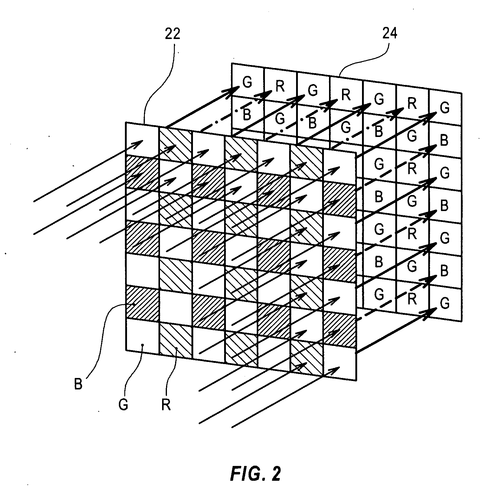
[0082]The imaging assembly 20 has an image sensor 24 with a two-dimensional arrangement of multiple fine imaging elements for converting the light intensities into electric signals. A color filter array 22 is provided before the image sensor 24 and has a mosaic arrangement of fine color filters of R (red), G (green), and B (blue). The a...


PUM


Abstract

An image processing procedure receives mosaic image data and calculates vertical and horizontal-direction color difference components for each pixel. The image processing procedure subsequently selects an R pixel or a B pixel from the mosaic image data, and compares a variation of the vertical-direction color difference component with a variation of the horizontal-direction color difference component with regard to each of at least the selected pixels to detect edge directions of the at least selected pixels. The edge directions thus obtained are collected in an edge direction map, and then the edge directions are compared with the surrounding edge directions to remove edge noise in advance. The image processing procedure refers to the detected edge directions, and interpolates a missing color component in each pixel of the mosaic image data with the settings of one color component in each pixel in the mosaic image data.

Description

BACKGROUND[0001]1. Technical Field[0002]Embodiments of the present invention relate to techniques of generating image data with an imaging device, such as a digital camera. More specifically disclosed embodiments pertain to techniques of generating color image data by application of a color filter array having a mosaic arrangement of fine color filters of R (red), G (green), and B (blue) corresponding to three primary colors of light.[0003]2. Related Art[0004]With the advancement of digital techniques, images are increasingly processed as digital data (image data). Imaging devices such as digital cameras enable immediate output of captured images in the form of image data. Imaging devices are typically equipped with an electronic image sensor consisting of small elements for converting light intensities into electric signals. The imaging device focuses a captured image of a subject on the image sensor by means of an optical system and detects the light intensities in the individual ...

Claims


Application Information

Patent Timeline
IPC IPC(8): H04N5/228
CPCH04N2209/046H04N9/045H04N23/843H04N25/134
Inventor LUKAC, RASTISLAV
Owner 138 EAST LCD ADVANCEMENTS LTD
Learn More