Lens driving device and image forming apparatus

a driving device and lens technology, applied in the direction of optics, mountings, instruments, etc., can solve the problems of slipping, malfunction, and a large load being exerted

Inactive Publication Date: 2010-03-04
RICOH KK
View PDF1 Cites 6 Cited by
  • Summary
  • Abstract
  • Description
  • Claims
  • Application Information

AI Technical Summary

Benefits of technology

[0018]An object of the present invention is to provide, on a per lens basis, a cam fitting structure, which is capable of maintaining an impact resistance that is sufficient to satisfy a demand for a large degree of impact resistance within a photographic region, by way of a unified form that is created by a mold, and with a unified form comprising a cam groove shape that does not include an undercut.

Problems solved by technology

An exertion of such an impact upon the lens barrel results in a tremendous load being exerted in turn upon the cam follower portion by way of a member that configures the lens barrel.
Given that the cam follower portion is fitted at an incline with respect to an axial direction of the lens barrel, the load being exerted upon the axial direction of the lens barrel thus causes a slippage to occur, the rotational cylinder or the fixed cylinder are deformed by being pressed by the cam follower, the cam follower becomes misaligned from the cam groove, and a malfunction may arise.
Given such a configuration as is described herein, two cam followers are required to mutually regulate a relative positional relationship between the two frame members, and the requirement of the two cam followers results in an increase in a quantity of components and an enlargement of a space required to house the components.
Furthermore, if the respective positions of the two cam followers are even slightly flawed in their precision, either a compression force or a pulling force will be exerted between the two cam grooves by the two cam followers.
As a result, it is necessary to exert a tremendous quantity of force in order to cause the configuration to operate, which is a factor that gives rise to a malfunction.
As described herein, however, according to the invention disclosed according to Japanese Patent Application Laid Open No. 2003-84185 and the invention disclosed according to Japanese Patent Application Laid Open No. 2002-90611, two cam followers are required to regulate the relative positional relationship between the two respective frame members, resulting in an increase in the number of components and a greater space required for the configurations.
A further problem is that if the respective positions of the two cam followers are even slightly flawed in their precision, it is necessary to exert a tremendous quantity of force in order to cause the configuration to operate, which may easily provide a factor that gives rise to a malfunction.

Method used


Image

  • Lens driving device and image forming apparatus
  • Lens driving device and image forming apparatus
  • Lens driving device and image forming apparatus

Examples


Embodiment Construction

[0031]An embodiment of a lens driving device and an image forming apparatus, such as a camera, according to the present invention will be described in detail hereinafter, with reference to the accompanying drawings.

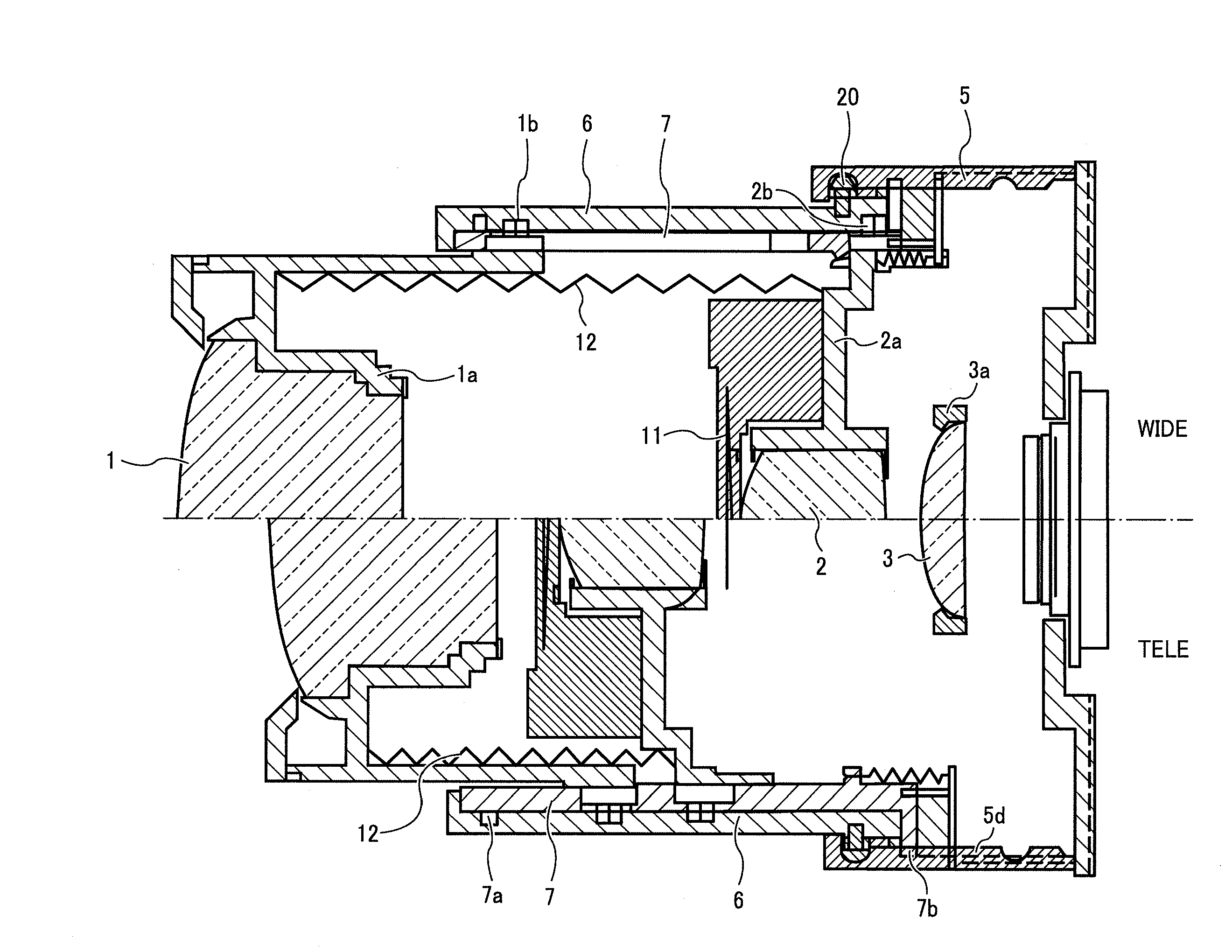
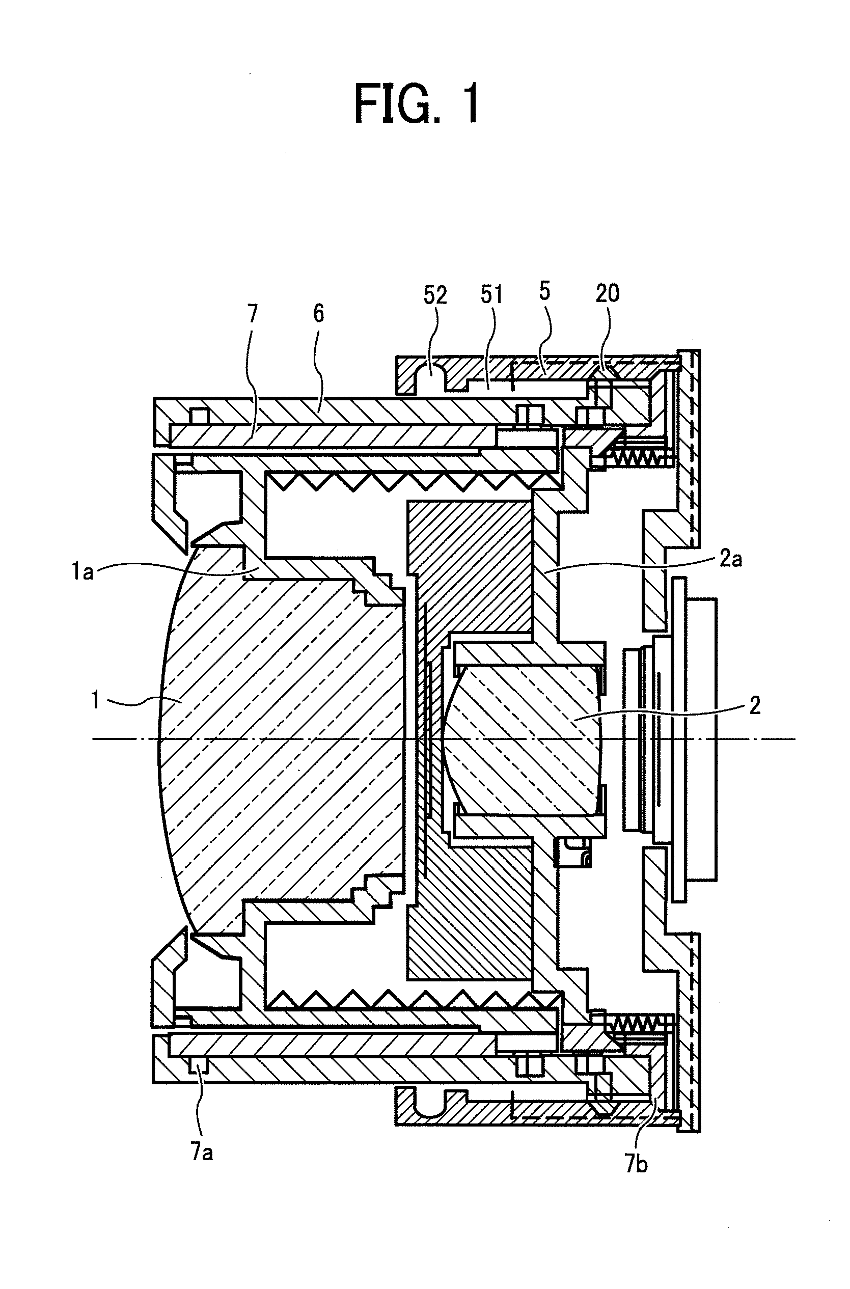
[0032]FIG. 1 illustrates a lens driving device according to the present invention, in an instance of an image forming apparatus, such as a camera, with a lens barrel of a zoom lens attached, with the lens driving device in a state of being collapsed within the image forming apparatus. FIG. 2 illustrates a state of the lens barrel of the zoom lens when photography is possible. An upper portion of FIG. 2 depicts a wide angle state, and a lower portion of FIG. 2 depicts a telephoto state.

[0033]The lens driving device shown in FIG. 1 and FIG. 2 includes a plurality of lens groups, and the plurality of lens groups, as an instance, are formed from a first lens group 1, a second lens group 2, and a third lens group 3. A change in a magnification, or put another way, a change in ...


PUM


Abstract

A lens driving device includes a lens, a lens frame configured to support the lens, a drive mechanism configured to cause the lens frame to move upon an optical axis, and a fixed member configured to support the drive mechanism. The drive mechanism includes a rotational cylinder capable of moving upon the optical axis, a cam part on the fixed member and a cam follower which is formed on the rotational cylinder fitting with the cam part and has a conical portion and a cylindrical portion. The cam part includes a tapered cam groove formed such that the rotational cylinder extends in the optical axis upon a range whereupon the rotational cylinder moves from the collapsed state to a photography state and a planar surface formed such that the rotational cylinder does not move upon the optical axis upon the photography range, even if the rotational cylinder rotates. The conical portion fits with the cam groove of the cam part upon the range whereupon the rotational cylinder moves upon the optical axis, and the cylindrical portion fits with the planar surface of the cam part upon the range whereupon the rotational cylinder does not move upon the optical axis.

Description

CROSS-REFERENCE TO THE RELATED APPLICATION[0001]This application is based on and claims the priority benefit of Japanese Patent Application No. 2008-217573, filed on Aug. 27, 2008, the disclosure of which is incorporated herein by reference in its entirety.BACKGROUND OF THE INVENTION[0002]1. Field of the Invention[0003]The present invention relates to a lens driving device and an image forming apparatus, and, more specifically to a lens driving device, which enables making a fixed cylinder provided with a cam groove, of a resin, has a high precision of a position of a lens group upon a region where photography may be performed, and prevents a malfunction from arising, such as might be caused by an impact upon the lens driving device, and an image forming apparatus including the lens driving device so configured.[0004]2. Description of the Related Art[0005]In recent years, it is common for a large number of photographic lenses that are employed in various types of cameras to include ...

Claims


Application Information

Patent Timeline
Patent Type & Authority Applications(United States)
IPC IPC(8): G02B7/04
CPCG02B7/04
Inventor IWASAKI, TETSUYA
Owner RICOH KK
Why Eureka
Try Eureka