Solenoid

a solenoid and insulating plate technology, applied in the field of solenoid, can solve the problems of high cost, and achieve the effect of saving material and cost, and ensuring sufficient impact resistan

Inactive Publication Date: 2005-09-01
NASS MAGNET GMBH
View PDF5 Cites 0 Cited by
  • Summary
  • Abstract
  • Description
  • Claims
  • Application Information

AI Technical Summary

Benefits of technology

[0005] The object of the invention is therefore to improve the magnet coil having an outer casing of plastics material to the effect that material and costs can be saved in ensuring sufficient impact resistance.

Problems solved by technology

However, additional material is required for the purpose, which gives rise to higher costs.

Method used


Image

  • Solenoid
  • Solenoid

Examples


Embodiment Construction

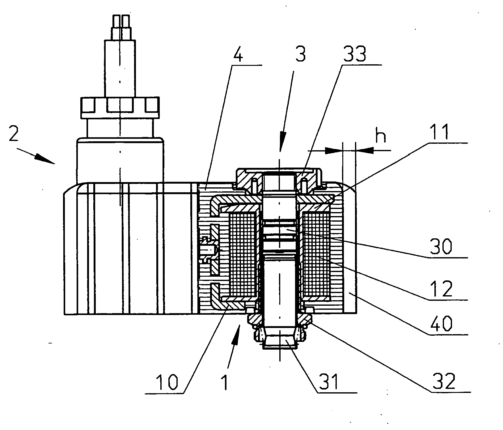
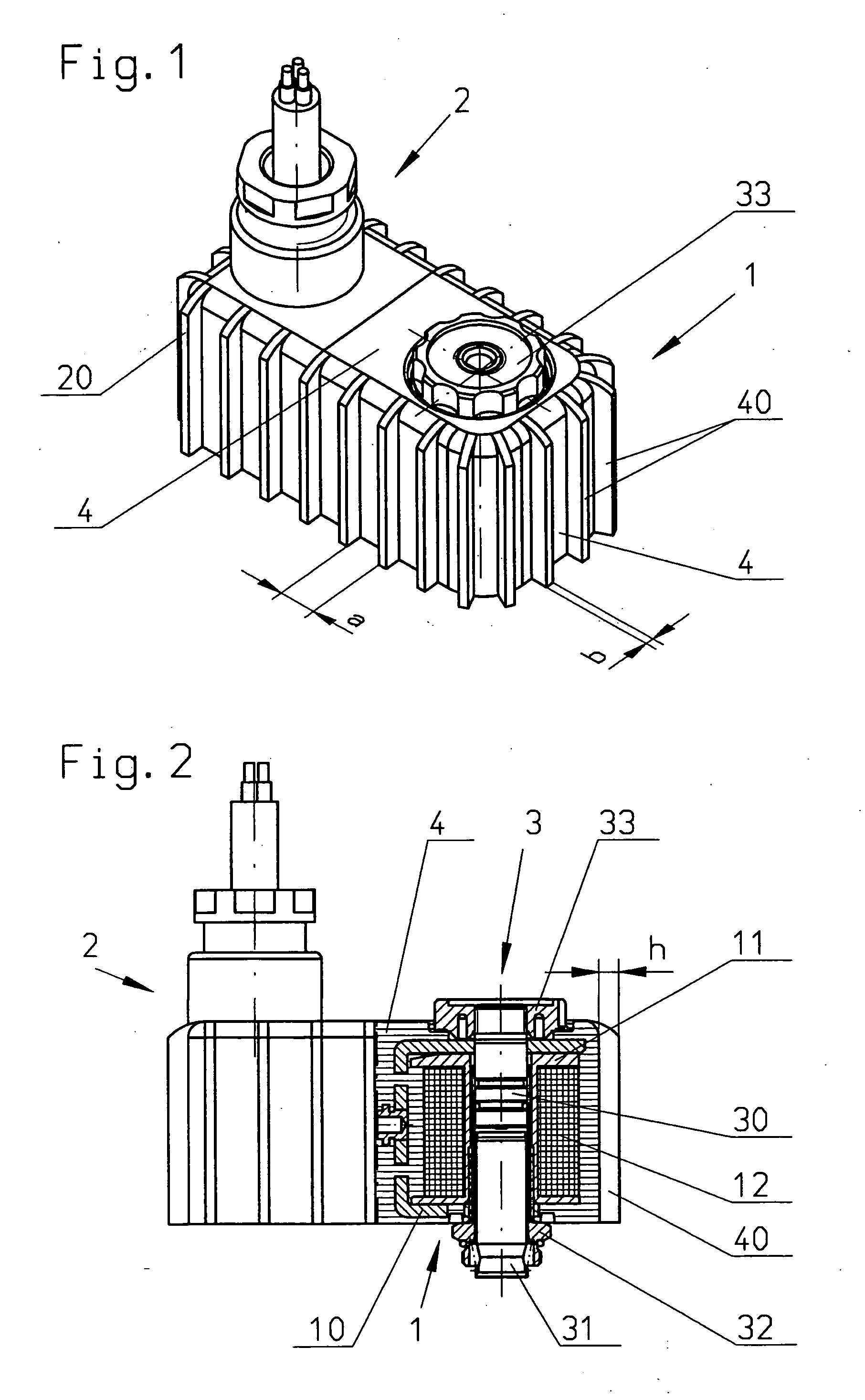
[0014]FIG. 1 shows a magnet coil (solenoid) 1 and an electrical connector housing 2 which are connected securely to each other. The coil 1 shown in more detail in FIG. 2 substantially comprises a yoke 10, a coil body 11 and a coil winding 12. Also shown are the components of an armature system 3 which, in detail, comprises a magnet core 30, an armature 31, an armature guide 32 and a securing nut 33.

[0015] The magnet coil 1 also has an outer casing 4 of plastics material which is normally manufactured by an injection molding process. A plurality of ribs 40 are also provided on the outside of the casing 4 as protection against impact.

[0016] In the embodiment shown, the ribs are formed by fins whose width b is smaller than their height h. The ratio of the distance a to the height h of the ribs is preferably in the range of from 1 to 2.

[0017] Within the scope of the invention, other configurations of the ribs are of course also possible. The form of the ribs is advantageously selecte...


PUM

PropertyMeasurementUnit
temperaturesaaaaaaaaaa
widthaaaaaaaaaa
heightaaaaaaaaaa

Abstract

A solenoid for use as a magnet coil has an outer casing of plastics material, a plurality of ribs being provided on the outside of the casing as protection against impact. The material and costs of the magnetic coil can be saved while ensuring sufficient impact resistance.

Description

FIELD OF THE INVENTION [0001] The invention relates to a solenoid having an outer casing of plastics material for use as a magnet coil. BACKGROUND OF THE INVENTION [0002] Magnet coils (solenoids) for hazardous areas have to satisfy an impact test according to the Standards EN 50 014 and EN 50 028. In this test the areas exposed to impact are hit vertically with a hemispherical test piece. [0003] Special measures must be taken in order to satisfy this regulation, especially in the case of low temperatures (for example −50° C.) , because the casing must not have any cracks and the internal electrical components, especially the winding, have to be protected. [0004] In order to ensure sufficient impact resistance, the plastics casing is usually reinforced accordingly. However, additional material is required for the purpose, which gives rise to higher costs. SUMMARY OF THE INVENTION [0005] The object of the invention is therefore to improve the magnet coil having an outer casing of plas...

Claims


Application Information

Patent Timeline
Patent Type & Authority Applications(United States)
IPC IPC(8): H02K33/16H01F7/06H01F7/128H01F27/02
CPCH01F7/06H01F27/022H01F7/128
Inventor HEINEMANN, ARNDTLEUSCHNER, WERNER
Owner NASS MAGNET GMBH
Why Eureka
Try Eureka