Illuminated handle bar grip

a technology of illuminated handle bars and led indicators, which is applied in the direction of lighting elements, cycle equipments, steering devices, etc., can solve the problems of easy damage to the increased illumination element, insufficient light emission of leds, and inability to increase the visibility of the rider, etc., to achieve simple replacement of batteries and easy installation.

Inactive Publication Date: 2010-03-04
WANG WENG SHIH
View PDF5 Cites 20 Cited by
  • Summary
  • Abstract
  • Description
  • Claims
  • Application Information

AI Technical Summary

Benefits of technology

[0013]The handlebar grip (1) consists of a cover (11) pervious to light and a grip (12) pervious to light. When the light emitting device (3) inside the grip (12) lights up the grip (12), which is sufficient to signify warning signs. It may replace the same to give off light only on the enlarged end of '590.
[0014]The handlebar grip (1) is easy to install to both ends of the handlebar of the vehicle. Replacement of batteries is simple also any maintenance is easy to be made.
[0015]The handlebar grip (1) can be added with various accessories, such as electro luminescence (EL) (i.e. a conventional double-insulated one in which the luminescence film is sandwiched i

Problems solved by technology

Installation of either the enlarged end with illumination element or the hidden heater with LED indicators is not so easy to increase the visibility of the rider.
Since the enlarged end is substantially designed to lengthen and enlarge the h

Method used


Image

  • Illuminated handle bar grip
  • Illuminated handle bar grip
  • Illuminated handle bar grip

Examples


first embodiment

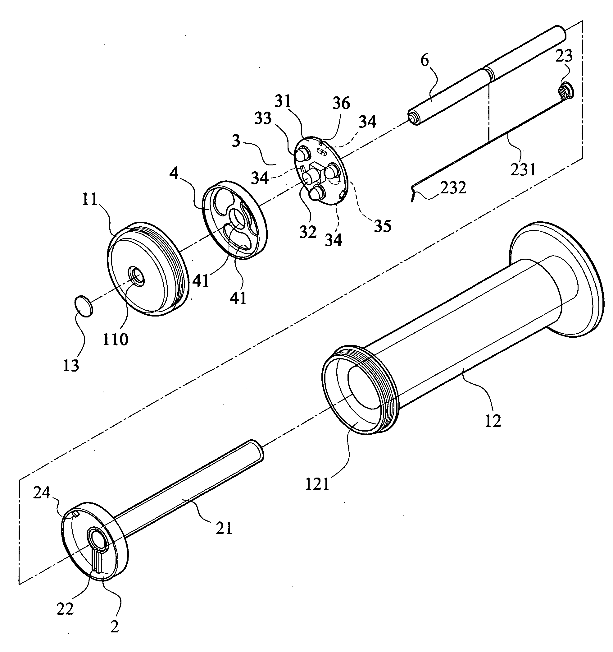
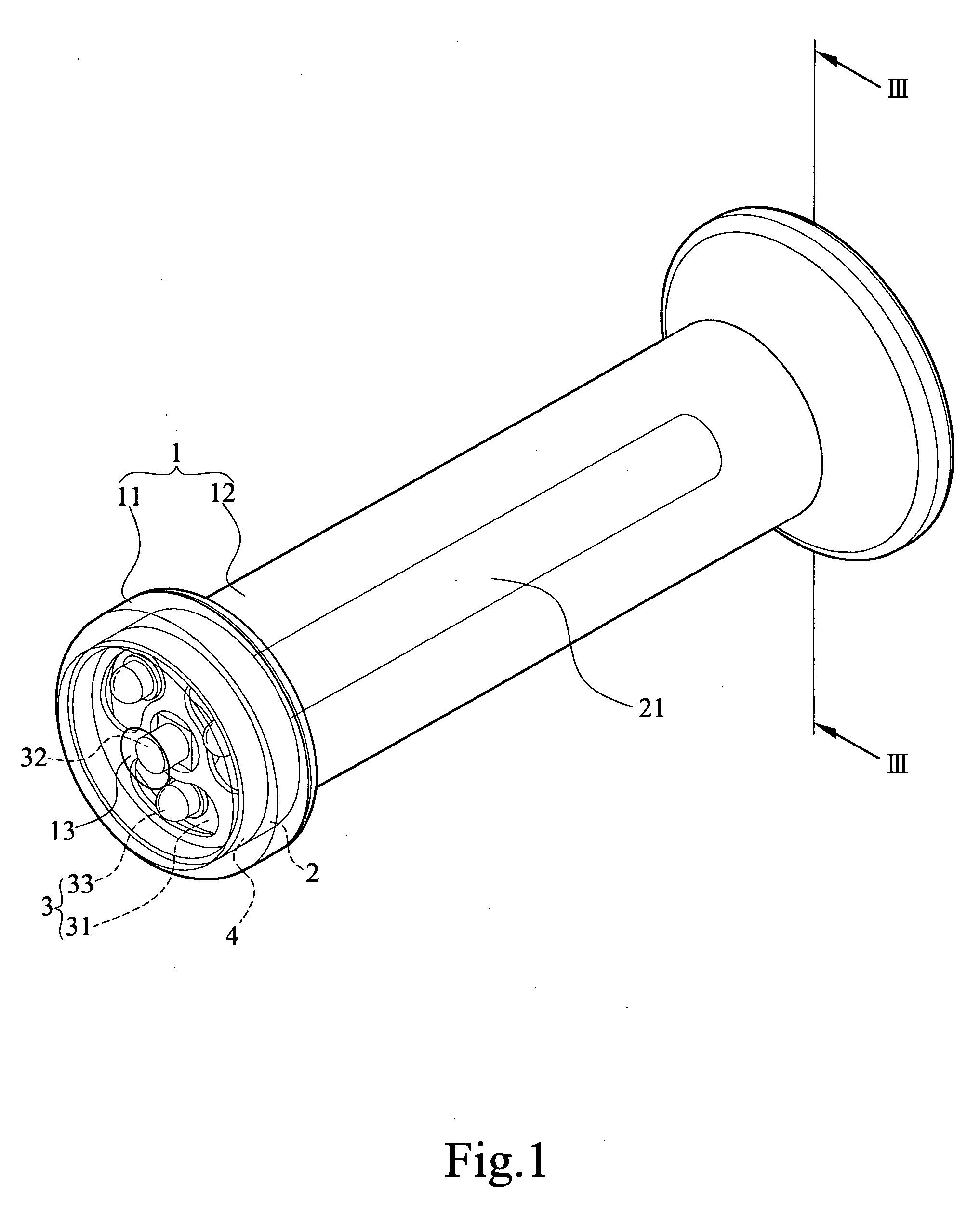
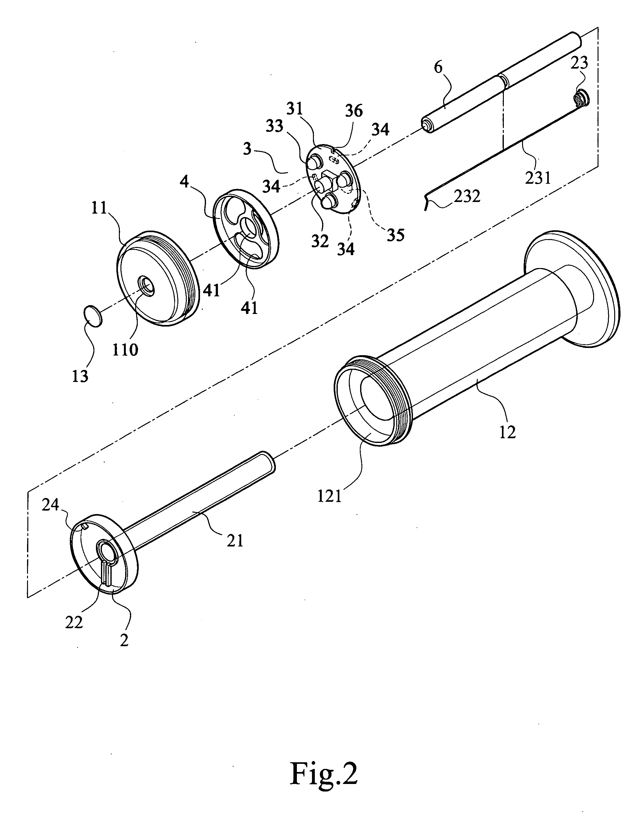
[0035]As shown in FIGS. 1˜3, an illuminated handlebar grip (1) comprises a grip (12) pervious to light, a first open end of the grip (12) accommodates a handlebar (9) received therein, a second closed end of the grip (1) is formed with a container (121); a battery seat (2) pervious to light disposed inside the container (121), a second end of said battery seat (2) is extended inside the grip (12) to form a cylindrical battery chamber (21) for receiving batteries (6); an outside diameter of said battery chamber (21) is smaller than an inside diameter of said handlebar (9); and a light emitting device (3) installed inside the battery seat (2), said batteries (6) supply power to the light emitting device (3), which is composed of a printed circuit board (PCB) (31), a switch (32) disposed on the PCB to turn on / off the light emitting device (3), a plurality of light emitting diodes (LEDs) (33, 34) are disposed on both first and second sides of the PCB (31) relatively, and an integral cir...

second embodiment

[0048]As shown in FIGS. 16 and 17, an illuminated handlebar grip (1) comprises a grip (12) pervious to light, a first open end of the grip (12) accommodates a handlebar (9) received therein, a second closed end of the grip (1) is formed with a container (121); a battery seat (2) pervious to light disposed inside the container (121); and a light emitting device (3) installed inside the container (121); the light emitting device (3) is composed of a printed circuit board (PCB) (31), a switch (32) disposed on the PCB to electrify the light emitting device, a plurality of light emitting diodes (LEDs) (33, 34) are disposed on both first and second sides of the PCB (31) relatively, and an integral circuit (IC) programmed with several effects to flash said LEDs (33, 34) in continuous sequence; said PCB (31) is connected to a power line (37) passed through the grip (12), the power line (37) is further electrically connected to a vehicle battery or an electric switch of turn light; and a cov...


PUM


Abstract

An illuminated handlebar grip (1) can be lit up thoroughly to improve two-wheeled vehicle safety comprising: a grip (12) accommodates a handlebar (9) received therein; a battery seat (2) is disposed inside the container (121) which is formed in the second close end of the grip (12), and is covered up by a cover (11) coupled to a second end of said grip (12); said battery seat (2) is extended inside the grip (12) to form a cylindrical battery chamber (21) for receiving batteries (6); a light emitting device (3) installed in the battery seat (2); and a positioning cover (4) provided between the cover (11) and PCB (31) to prevent any displacement of the PCB (31).

Description

FIELD OF THE INVENTION[0001]The present invention is related to an illuminated handle bar grip, particularly for two-wheeled vehicle such as bicycle, motorcycle or scooter.DESCRIPTION OF PRIOR ART[0002]Two wheeled vehicle includes bicycle, motorcycle, or scooter, being driven at night, or making tight turns, may give off light to signify warning signs to the coming cars or following cars or pedestrians. Persons skilled in the art have provided light emissions from handle bar grip to increase the visibility of cyclists or motorcyclists or the like.[0003]Such as U.S. Pat. No. 6,308,590 entitled “Handle bar device” to Joseph Berto on Oct. 30, 2001 (hereinafter '590), it disclosed an enlarged end of the handle bar has a perimeter greater than the handlebar grip without the rider's hand slipping off the end of the grip and with less fatigue. An illumination element provides additional lighting to the vehicle for greater safety for the rider. A conical frustum camming element has protrusi...

Claims


Application Information

Patent Timeline
IPC IPC(8): B62J6/00
CPCB62J6/00B62K21/26B62J6/003B62J6/015B62J6/26
Inventor WANG, WENG-SHIH
Owner WANG WENG SHIH
Why Eureka
Try Eureka