Fastening apparatus and system for detecting axial force thereof

a technology of axial force and fastening apparatus, which is applied in the direction of threaded fasteners, load-modified fasteners, screws, etc., can solve the problems of increasing the weight and cost of the apparatus, and the conventional techniques relating to fastening fail to significantly reduce the troubles caused, so as to achieve labor savings

Inactive Publication Date: 2010-03-04
FURUKAWA ELECTRIC POWER SYST
View PDF3 Cites 54 Cited by
  • Summary
  • Abstract
  • Description
  • Claims
  • Application Information

AI Technical Summary

Benefits of technology

[0026]Furthermore, by applying the system or method according to the present invention, it is possible to monitor accidents such as an unexpected force (significant axial force change) acting upon the fastening section. For instance, adopting this technique in important security units such as nuclear equipment, automobile, aircraft, and railroad contributes to prevention of accidents and determination of causes of accidents.
[0027]In addition, in the case where a bolt to which the technique of the present invention is applied is used to fix a rail to a railroad tie, the looseness of the bolt can be inspected at high speed on a regular basis by installing an appropriate reader in a high-speed test vehicle, which contributes to labor savings and safety improvements.

Problems solved by technology

As described above, the conventional techniques relating to fastening fail to significantly reduce troubles caused by looseness of a fastening section and the like.
This leads to increases in apparatus weight and cost.

Method used


Image

  • Fastening apparatus and system for detecting axial force thereof
  • Fastening apparatus and system for detecting axial force thereof
  • Fastening apparatus and system for detecting axial force thereof

Examples


Embodiment Construction

[0031]The following provides a detailed description of an embodiment of a fastening apparatus and a system for detecting an axial force thereof according to the present invention, with reference to attached drawings.

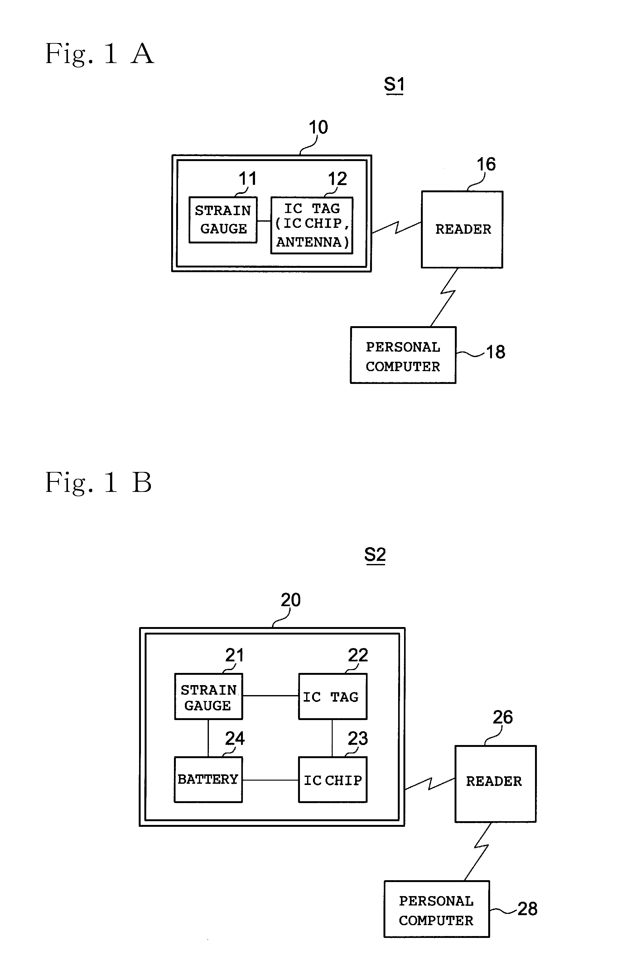
[0032]FIG. 1 is a block diagram of an axial force detecting system (S1, S2) of a fastening apparatus.

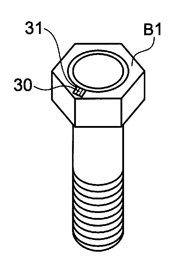
[0033]The axial force detecting system S1 shown in FIG. 1A has means for detecting a fastening axial force of a fastening apparatus including a bolt or a nut, and is composed of a structure in which “an axial force detector 10—a reader 16—a personal computer 18” are connected together. “The axial force detector 10—the reader 16” are connected wirelessly, and “the reader 16—the personal computer 18” are connected wirelessly or wiredly.

[0034]The axial force detector 10 includes a strain gauge 11 that is attached at a predetermined location to detect an axial force value of the fastening apparatus, and an IC tag 12 that is connected to the strain gauge 11 and wirelessly tran...


PUM


Abstract

A detecting system of a fastening apparatus that detects an axial force of the fastening apparatus including a bolt or a nut. The detecting system includes an axial force detector including a strain gauge and an IC tag, the strain gauge being provided at a predetermined location to detect an axial force value of the fastening apparatus, and the IC tag being connected to the strain gauge and wirelessly transmitting the detected axial force value and unique identification information. Power is supplied to the axial force detector. A reader reads data transmitted from the axial force detector.

Description

BACKGROUND OF THE INVENTION[0001]1. Field of the Invention[0002]The present invention relates to a fastening apparatus for fastening a member using a fastener such as a bolt or a nut, and to a detecting system of the fastening apparatus for detecting and managing an axial force during fastening.[0003]2. Description of the Related Art[0004]Many fastening means are intended to keep a constant axial force in order to enhance reliability of a fastening section where a fastener such as a bolt or a nut is fastened.[0005]For example, such fastening means include: 1) fastening using a torque wrench; 2) incorporating a breakaway mechanism; and 3) adopting an SP locknut (constant axial force locking nut).[0006]However, these fastening means have various disadvantages.[0007]In fastening using a torque wrench, even when a bolt or a nut is fastened to the same torque set by the torque wrench, each obtained axial force varies because the bolt or the nut is affected by a difference in friction coe...

Claims


Application Information

Patent Timeline
Patent Type & Authority Applications(United States)
IPC IPC(8): F16B31/02
CPCF16B31/02B25B23/14G01L5/24G01B7/16
Inventor NISHIDA, EIJIHASHIMOTO, FUMIYOSHI
Owner FURUKAWA ELECTRIC POWER SYST
Why Eureka
Try Eureka