Micro valve apparatus using micro bead and method for controlling the same

a valve and micro-bead technology, applied in the direction of analytical instruments, laboratory glassware, chemical indicators, etc., can solve the problems of large amount of electricity required to turn on or off the valve, the apparatus cannot overcome the problems of the thin-film type valve and the problem of precisely controlling the flow rate, and the design of such a valve for the thin-film type assay apparatus is complicated. , to achieve the effect of increasing the rate of fluid flowing through the hole 10

Inactive Publication Date: 2010-03-04
SAMSUNG ELECTRONICS CO LTD
View PDF17 Cites 4 Cited by
  • Summary
  • Abstract
  • Description
  • Claims
  • Application Information

AI Technical Summary

Benefits of technology

[0014]In one aspect, the present invention provides a micro valve apparatus comprising: channels as flow paths of a fluid; a hole which interconnects the channels; a body in which the channels and the hole are formed; upper and lower electromagnets mounted on the top and bottom surfaces of the body, respectively, opposite to each other, which generate a magnetic force with the application of power; and a microbead which is moved upward or downward by on / off control of the power applied to the upper and lower electromagnets, to open and close the hole, thereby controlling fluid flow and its rate.
[0015]Alternatively, the present invention provides a micro valve apparatus comprising: channels as flow paths of a fluid; a hole which interconnects the channels; a body in which the channels and the hole are formed; upper and lower electrode plates mounted on the top and bottom surfaces of the body, respectively, opposite to each other, which generate an electric field with the application of power; and a charged microbead which is moved upward or downward by controlling the direction in which power is applied to the upper and lower electrode plates, to open and close the hole, thereby controlling fluid flow and its rate.

Problems solved by technology

However, designing such a valve for a thin film type assay apparatus is complicated.
However, these apparatuses failed to overcome the problems of the thin film type valve and to precisely control flow rate.
Also, a large amount of electricity is required to turn on or off the valve and move the cylinder or flange.
The valve using the electromagnet cannot be constructed as a thin film type valve due to the size of the electromagnet.
The valve generates excess heat by consuming a large amount of electricity.

Method used


Image

  • Micro valve apparatus using micro bead and method for controlling the same
  • Micro valve apparatus using micro bead and method for controlling the same
  • Micro valve apparatus using micro bead and method for controlling the same

Examples


Embodiment Construction

[0059]The present invention will be described in greater detail with reference to the following embodiments. The following embodiments are for illustrative purposes and are not intended to limit the scope of the invention.

[0060]FIG. 4 shows a plan view and a sectional view, taken along line a-b, of an nucleic acid assay device constructed as a lab-on-a-chip according to an embodiment of the present invention, where the micro valve apparatus using a microbead according to the present invention is installed in a thin disk type apparatus 200. The thin disk type apparatus 200 may be a general CD-ROM, DVD, bio-CD, or bio-DVD.

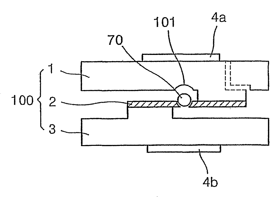
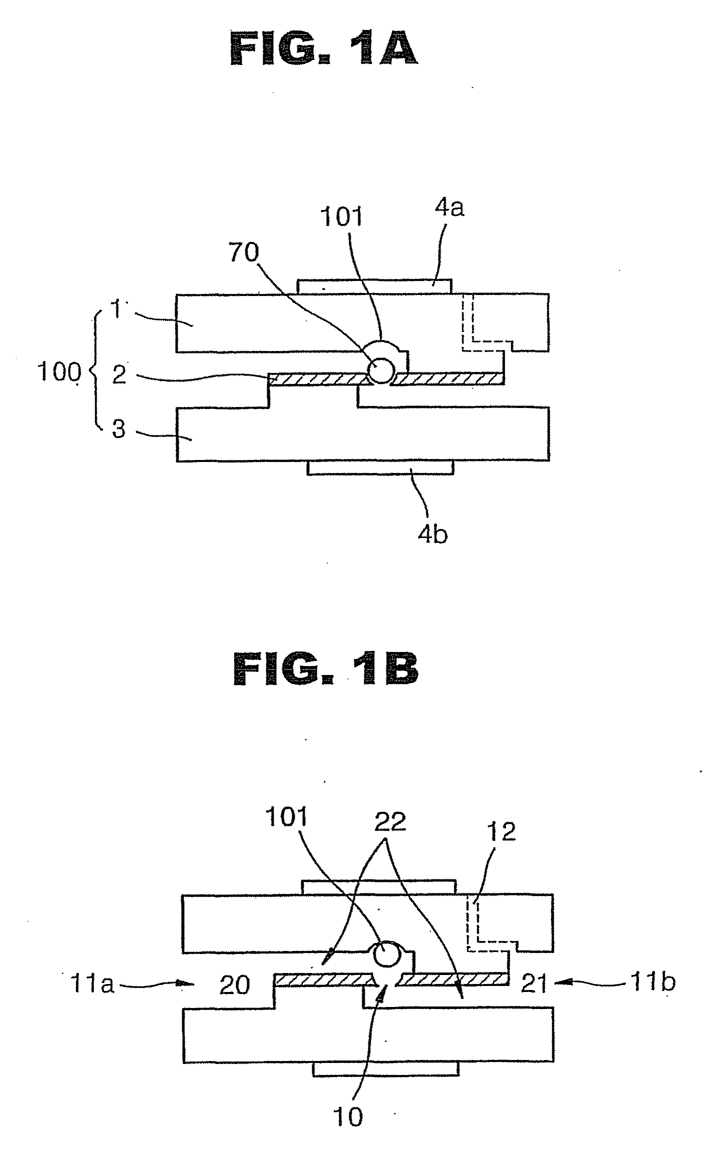
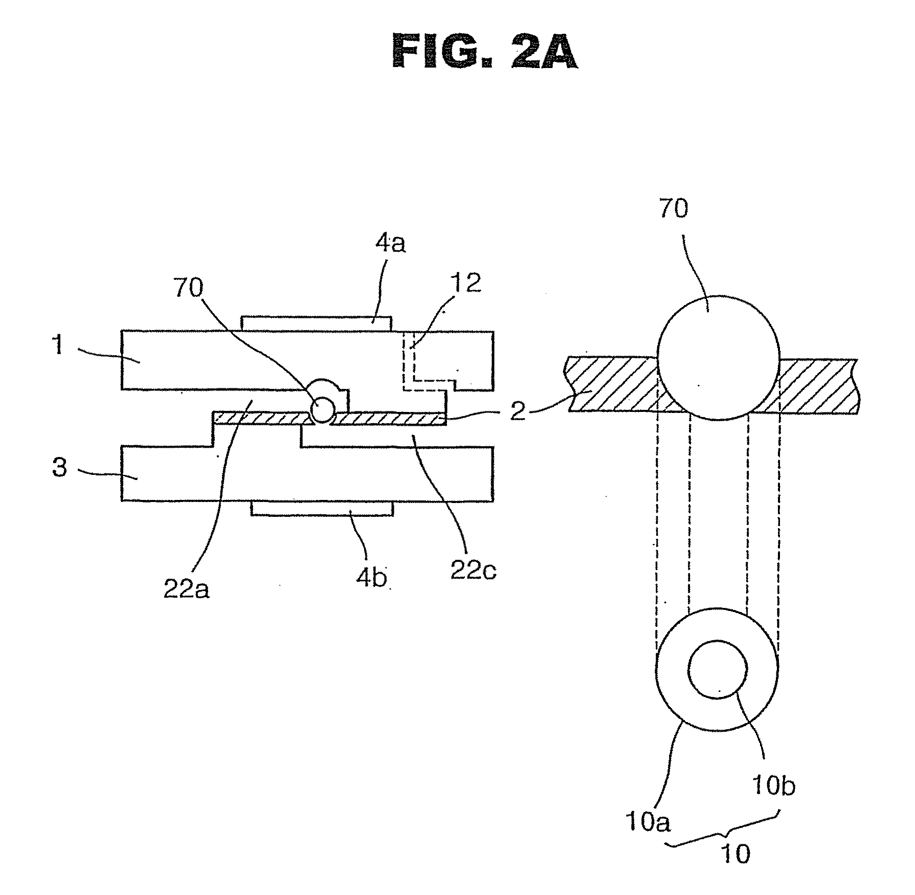
[0061]Reference numeral 100 denotes a body constructed by binding the upper substrate 1, the intermediate substrate 2, and the lower substrate 3 together. Microbeads 70a, 70b, and 70c are independently moved by the magnetic force generated by electromagnetic pairs 190a 190b, 191a and 191b, and 192a and 192b, respectively, to open or close holes. Reference numeral 120...


PUM

PropertyMeasurementUnit
diameteraaaaaaaaaa
diameteraaaaaaaaaa
magnetic forceaaaaaaaaaa

Abstract

A micro (thin film type) valve apparatus for controlling fluid flow and its rate using microbead and a method for controlling the apparatus are provided. The microbead is moved by the magnetic forge generated by upper and lower electromagnets disposed on the top and bottom surface of the body or by the electric field generated by upper and lower electrode plates disposed on the top and bottom surface of the body, thereby interconnecting or blocking flow channels in the body. The micro valve apparatus and the method for controlling the same are suitable for thin film type diagnostic assay devices, such as lab-on-chips, protein chips, or DNA chips, for detecting small quantities of analytes in fluids, and more suitable for interconnecting or blocking channels formed in thin disc type apparatus, including general CD-ROMs, DVDs, bioCDs, and bio DVDs.

Description

CROSS-REFERENCE TO RELATED APPLICATIONS[0001]This application is a U.S. continuation application filed under 35 USC 1.53(b) claiming priority benefit of U.S. Ser. No. 10 / 479,004 filed in the United States on Nov. 25, 2003, which is based on a 371 application of PCT / KR / 02 / 01035 filed on May 31, 2002, published on Dec. 5, 2002 under Publication No. WO 02 / 097422 A1 which claims priority benefits from Korean Patent Application No. KR 2001 / 31284 filed on May 31, 2001, the disclosures of which are incorporated herein by reference.BACKGROUND[0002]1. Field[0003]The present invention relates to the field of controlling fluid flow and its rate in a micro assay device for the detection of a small quantity of an analyte in a fluid. More particularly, the present invention relates to a micro (thin film type) valve apparatus using a microbead to control fluid flow or its rate, and a method for controlling the micro valve apparatus.[0004]2. Description of the Related Art[0005]To date, for most dia...

Claims


Application Information

Patent Timeline
Patent Type & Authority Applications(United States)
IPC IPC(8): C12M1/34B01L99/00B01L3/00F16K31/06F15C3/06F15C5/00F16K99/00G01N35/00
CPCB01L3/502738B01L2200/10B01L2300/0806B01L2400/0633F15C3/06F16K99/0001G01N2035/00247F16K99/0023F16K99/0028F16K99/0046F16K2099/0078G01N35/00069F16K99/0013F16K31/06
Inventor YOO, JAE CHERN
Owner SAMSUNG ELECTRONICS CO LTD
Why Eureka
Try Eureka