Method and system for pre-programmed self-power microfluidic circuits

a microfluidic circuit and pre-programmed technology, applied in the field of microfluidic systems, can solve the problems of complex peripheral equipment, difficult to implement as low cost, robust and portable point-of-care systems, and antibodies that are not efficient at capturing bacteria

Active Publication Date: 2014-11-13
MCGILL UNIV
View PDF17 Cites 28 Cited by
  • Summary
  • Abstract
  • Description
  • Claims
  • Application Information

AI Technical Summary

Benefits of technology

[0031]It is an object of the present invention to address limitations in the prior art relating to microflui...

Problems solved by technology

To date a major challenge for the clinical use of “lab-on-a-chip” (LOAC) systems has been that they are generally complex and require sophisticated peripheral equipment, and as a result have proven much more difficult than anticipated to implement as low cost, robust and portable point-of-care systems.
However, most of these sensors rely on antibodies for capturing the bacteria on the surface, but antibodies are not efficient at capturing bacteria (bacteria are enormous compared to small molecules against which antibodies are commonly used), In addition, to date only a few biosensors may be integrated into LOAC systems in order to allow them to produce inexpensive LOAC systems which are easily amenable to miniaturization and mass production, and are potentially portable, using compact possibly hand-held instruments, using reusable or disposable detectors.
However, the isolation of CTCs is extremely challenging as they are significant even at ultralow concentrations of 5 cells per milliliter and the difficulty of separating them from white blood cells that are of similar size but present at concentrations of several million times higher, approximately 107 cells per milliliter.
However, a drawback of these type of microfluidic technologies developed to date was that their low flow rate typically resulted in isolation times of several hours.
This has limited their adoption within clinics to date as well as preventing their deployment in more consumer driven POC an...

Method used


Image

  • Method and system for pre-programmed self-power microfluidic circuits
  • Method and system for pre-programmed self-power microfluidic circuits
  • Method and system for pre-programmed self-power microfluidic circuits

Examples


Embodiment Construction

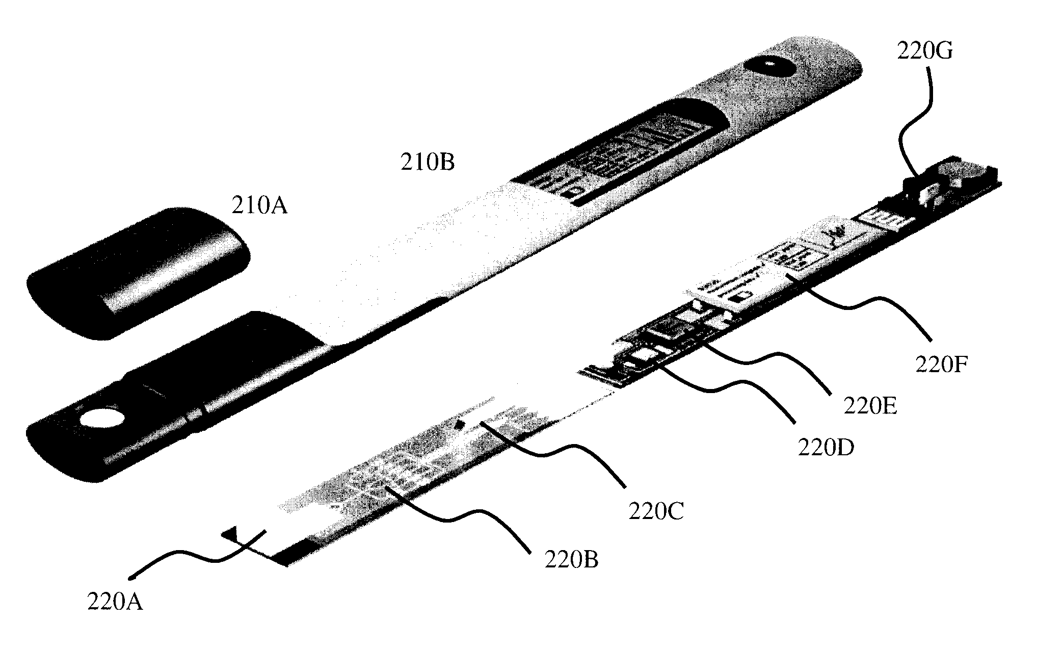
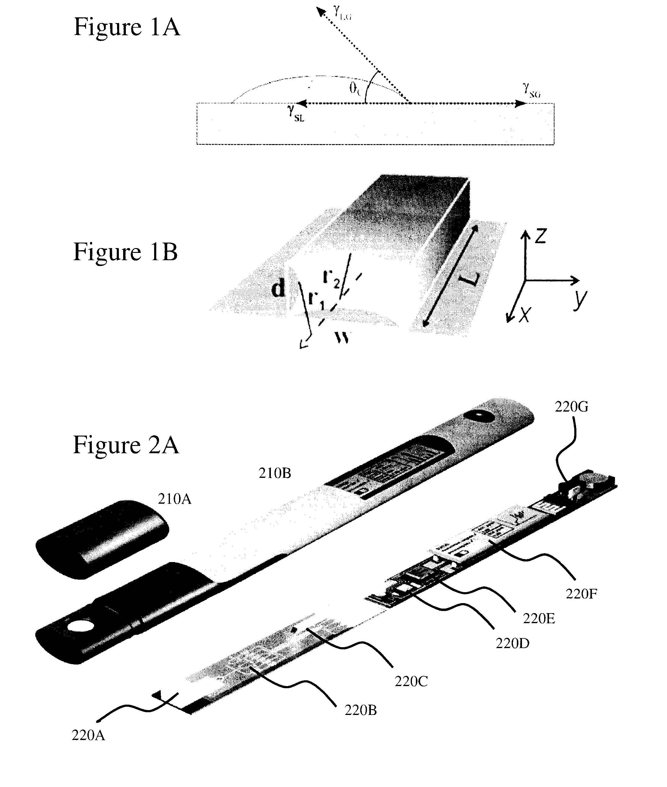
[0080]The present invention is directed to microfluidic systems and more particularly to pre-programmed self-powered microfluidic systems employing capillary elements.

[0081]The ensuing description provides exemplary embodiment(s) only, and is not intended to limit the scope, applicability or configuration of the disclosure. Rather, the ensuing description of the exemplary embodiment(s) will provide those skilled in the art with an enabling description for implementing an exemplary embodiment. It being understood that various changes may be made in the function and arrangement of elements without departing from the spirit and scope as set forth in the appended claims.

[0082]{AMEND FOR STANDARD TERMS IN SPECIFICATION} A “microfluidic circuit” (MICFLIC) as used herein and throughout this disclosure, refers to a capillary action based circuit employing microfluidic capillary structures which is self-powered and self-regulating through the designed performance of the microfluidic elements...


PUM


Abstract

A major challenge for the general use of “lab-on-a-chip” (LOAC) systems and point-of-care (POC) devices has been the generally complex and need for sophisticated peripheral equipment, such that it is more difficult than anticipated to implement low cost, robust and portable LOAC/POC solutions. It would be beneficial for chemical, medical, healthcare, and environmental applications to provide designs for inexpensive LOAC/POC solutions compatible with miniaturization and mass production, and are potentially portable, using compact possibly hand-held instruments, using reusable or disposable detectors. Embodiments of the invention address improved circuit elements for self-powered self-regulating microfluidic circuits including programmable retention valves, programmable trigger valves, enhanced capillary pumps, and flow resonators. Additionally embodiments of the invention allow for the flow direction within a microfluidic circuit to be reversed as well as for retention of reagents prior to sale or deployment of the microfluidic circuit for eased user use.

Description

CROSS-REFERENCE TO RELATED APPLICATIONS[0001]This patent application claims the benefit of U.S. Provisional Patent Application U.S. 61 / 528,853 filed Aug. 30, 2011 entitled “Microfluidic System using Capillary Effects.”FIELD OF THE INVENTION[0002]The present invention relates to microfluidic systems and more particularly to pre-programmed self-powered microfluidic systems employing capillary elements.BACKGROUND OF THE INVENTION[0003]Biological assays (commonly referred to as bioassays) are a type of scientific experiment. Bioassays are typically conducted to measure the effects of a substance on a living organism and exploit in many instances the concentration, purity or biological activity of a substance such as vitamin, hormone, and plant growth factor. While measuring the effect on an organism, tissue cells, enzymes or receptor bioassays may also process and / or compare a standard preparation, i.e. a reference. Bioassays may be qualitative or quantitative and are typically employed...

Claims


Application Information

Patent Timeline
IPC IPC(8): F16K15/18
CPCF16K15/18B01L3/50273B01L3/502738B01L3/502746B01L2200/0621B01L2200/16B01L2300/044B01L2300/048B01L2300/0816B01L2300/0867B01L2300/087B01L2300/0883B01L2300/0887B01L2400/0406B01L2400/0688B01L2400/0694B01L2400/086Y10T137/7837
Inventor JUNCKER, DAVIDSAFAVIEH, HOSSEINALI
Owner MCGILL UNIV
Why Eureka
Try Eureka