Method for recognizing a vertical misalignment of a radar sensor

a radar sensor and vertical misalignment technology, applied in the direction of structural/machine measurement, using reradiation, instruments, etc., can solve the problems of antenna diagram deviating strongly, misalignment cannot be recognized, and expensive radar sensors having this additional function

Inactive Publication Date: 2010-03-04
ROBERT BOSCH GMBH
View PDF10 Cites 21 Cited by
  • Summary
  • Abstract
  • Description
  • Claims
  • Application Information

AI Technical Summary

Benefits of technology

[0015]As an object, it may be advantageous to select moving objects, for example vehicles that are approaching or moving away, because in general the vertical position of stationary objects is unknown. Thus, for e

Problems solved by technology

Radar sensors having this additional function are expensive and are used only rarely in vehicles.
For vertical misalignment, this is not possible, because such radar sensors do not measure angles in the vertical direction, so that a misalignment cannot be recognized on the basis of trajectories.
If the vertical misalignment angle differs from 0°, the antenna diagram deviates strongly from the ideally used antenna diagram, and to this extent has only limited validity.
This method and device do not enable the compensation of misalignments that result for example during operation of the vehicle, such as damages to, for example, a fender in which the radar sensor is installed, or given a high trailer weight, which can r

Method used


Image

  • Method for recognizing a vertical misalignment of a radar sensor
  • Method for recognizing a vertical misalignment of a radar sensor
  • Method for recognizing a vertical misalignment of a radar sensor

Examples


Embodiment Construction

[0022]In FIGS. 1, 2, and 3, identical elements have been designated with identical reference characters.

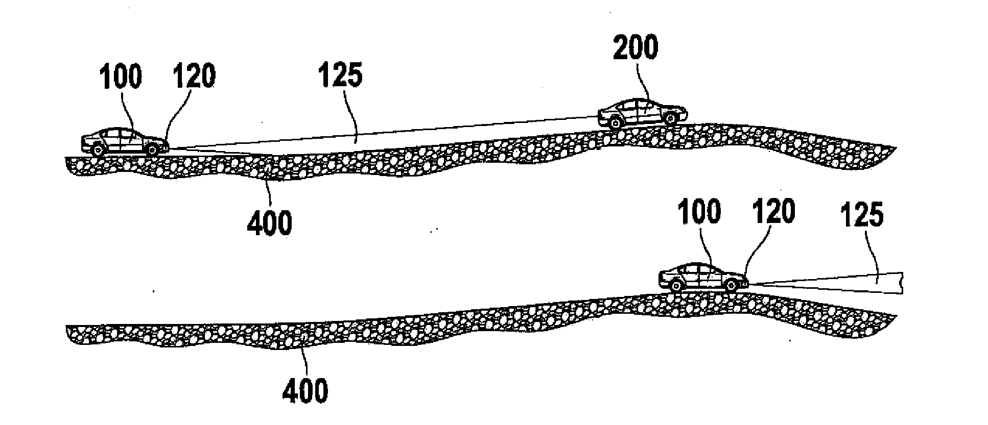
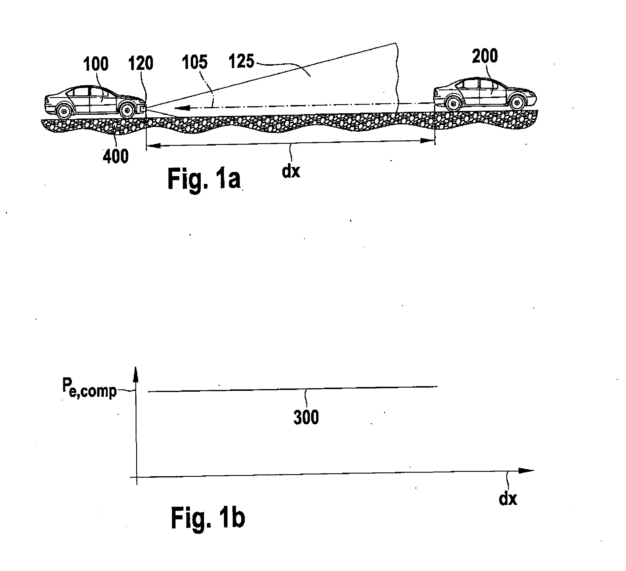
[0023]FIG. 1 schematically shows a vehicle 100 that has a properly adjusted radar sensor 120. This radar sensor 120 has a sector-pattern sensor field of view 125 that is aligned with mid-axis 105 of the vehicle. In this way, given a flat roadway 400 a vehicle 200 traveling in front of vehicle 100 can be recognized through acquisition and evaluation of the radar radiation reflected by vehicle 200. In FIG. 1b, receive power Pe, comp is shown over distance dx from vehicle 200 traveling in front, after compensation of the distance dependence and the dependence on the horizontal angle.

[0024]The antenna characteristic shows its highest sensitivity on mid-axis 105. The greater the deviation from mid-axis 105 is, the lower becomes the receive power from an object, e.g. vehicle 200 traveling in front of vehicle 100. Although a misalignment cannot be determined from the measured power becau...


PUM


Abstract

A method for recognizing a vertical misalignment of the radiation characteristic of a radar sensor of a control system for a motor vehicle, in particular of a driving speed and/or adaptive driving speed system, including the following steps: the receive power of the radar radiation reflected from an object is determined; the distance dependence and the horizontal angular dependence are compensated according to the radar equation; the functional dependence of the receive power, processed in this way, on the distance from the object is compared to an expected and stored curve of the receive power over the distance, and from this the vertical misalignment of the radiation characteristic of the radar sensor is inferred.

Description

FIELD OF THE INVENTION[0001]The present invention relates to a method, computer program and computer program product for recognizing a vertical misalignment of the radiation characteristic of a radar sensor, in particular a long-range radar system of a control system for a motor vehicle, in particular of a distance and / or driving speed control system.BACKGROUND INFORMATION[0002]Conventional methods and devices for recognizing misalignments, including those having a capability of self-correcting their sensor field of view, are available.[0003]Thus, for example, German Patent. Application No. DE 100 19 182 A1 describes a method and a device for determining a misalignment of the radiation characteristic of a sensor for speed and distance controlling of a vehicle that represents a combination of two separate methods. The two individual methods are selected such that the one method has advantages in the areas in which the other method functions poorly, so that the weaknesses of the one m...

Claims


Application Information

Patent Timeline
IPC IPC(8): G01S7/40G06F7/00G01S13/931
CPCG01S7/4026G01S13/931G01S2007/403G01S2007/4034G01S2007/4091G01S7/4034G01S7/403G01S7/4091
Inventor HOETZER, DIETERJORDAN, RUEDIGERSCHWINDT, OLIVER
Owner ROBERT BOSCH GMBH
Why Eureka
Try Eureka