Vehicle state estimating apparatus, suspension control apparatus and suspension system

a technology of vehicle state estimation and control apparatus, which is applied in adaptive control, cycle equipment, instruments, etc., can solve the problems of reducing the accuracy or impossibility of estimation, reducing the accuracy of estimating a motion state of the vehicle, and difficult to estimate the same control force as the actual control force, etc., to achieve accurate estimating the effect of the motion sta

Inactive Publication Date: 2010-03-04
HITACHI AUTOMOTIVE SYST LTD +1
View PDF24 Cites 38 Cited by
  • Summary
  • Abstract
  • Description
  • Claims
  • Application Information

AI Technical Summary

Benefits of technology

[0007]An object of the present invention is to provide a vehicle state estimating apparatus, a suspension control apparatus and a suspension system capable of accurately estimating a motion state of a vehicle.

Problems solved by technology

Unsatisfaction with these conditions may result in reduced estimation accuracy or impossibility of estimation.
However, if a suspension control apparatus and a suspension system employ a control suspension which generates variable control force, such as a semiactive damper or an active suspension, it is difficult to estimate a same control force as an actual control force due to the nonlinearity of such a suspension.
However, a control suspension is not a static system but a dynamic system.
Because time lag occurs in this way, the difference expands between an estimated control force and an actual control force accordingly, as a result of which accuracy of estimating a motion state of the vehicle is reduced and it becomes difficult to provide a desired control effect.

Method used


Image

  • Vehicle state estimating apparatus, suspension control apparatus and suspension system
  • Vehicle state estimating apparatus, suspension control apparatus and suspension system
  • Vehicle state estimating apparatus, suspension control apparatus and suspension system

Examples


Embodiment Construction

[0024]Hereinafter, a semiactive suspension system (suspension system) of a first embodiment of the present invention will be described with reference to the drawings.

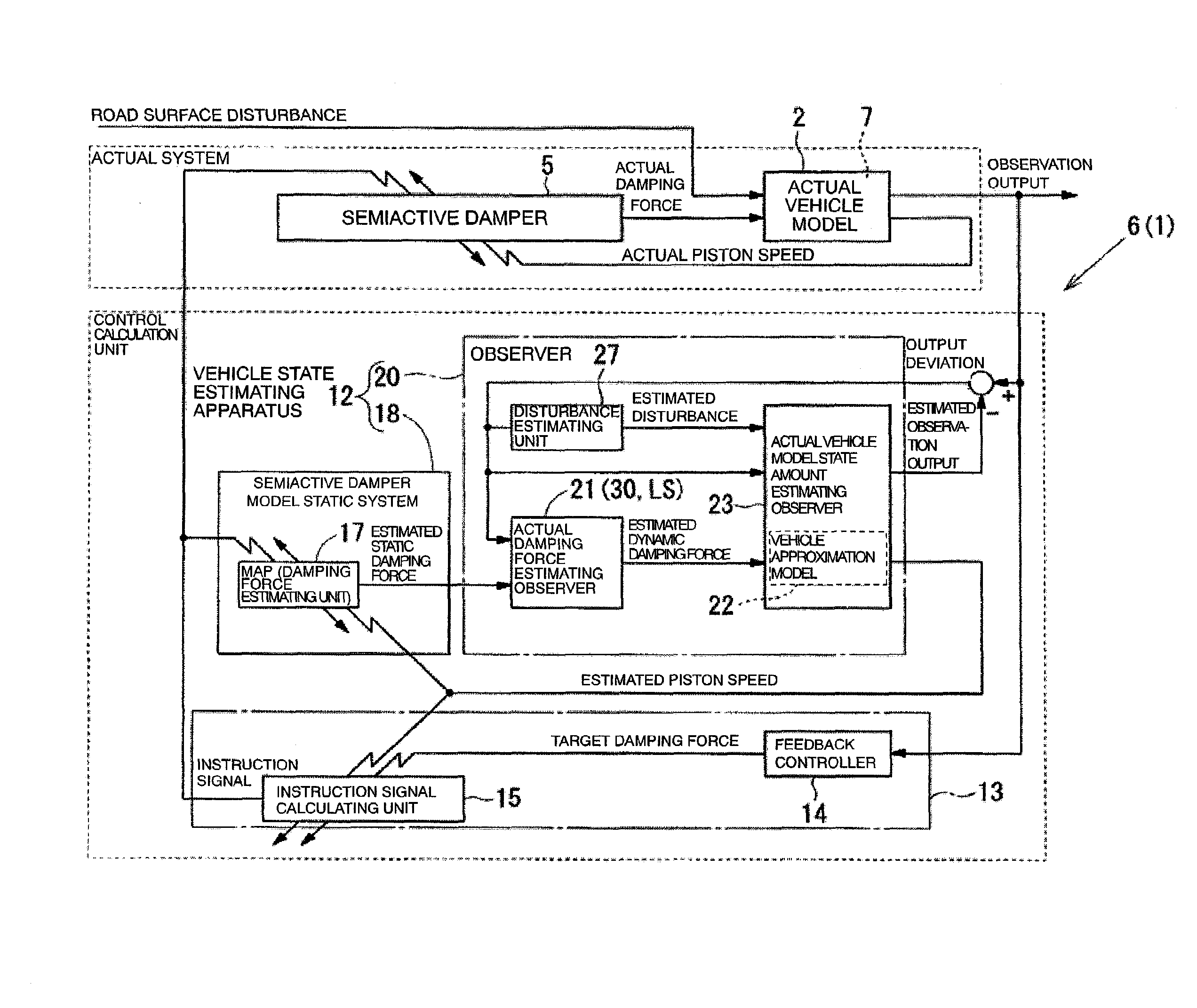
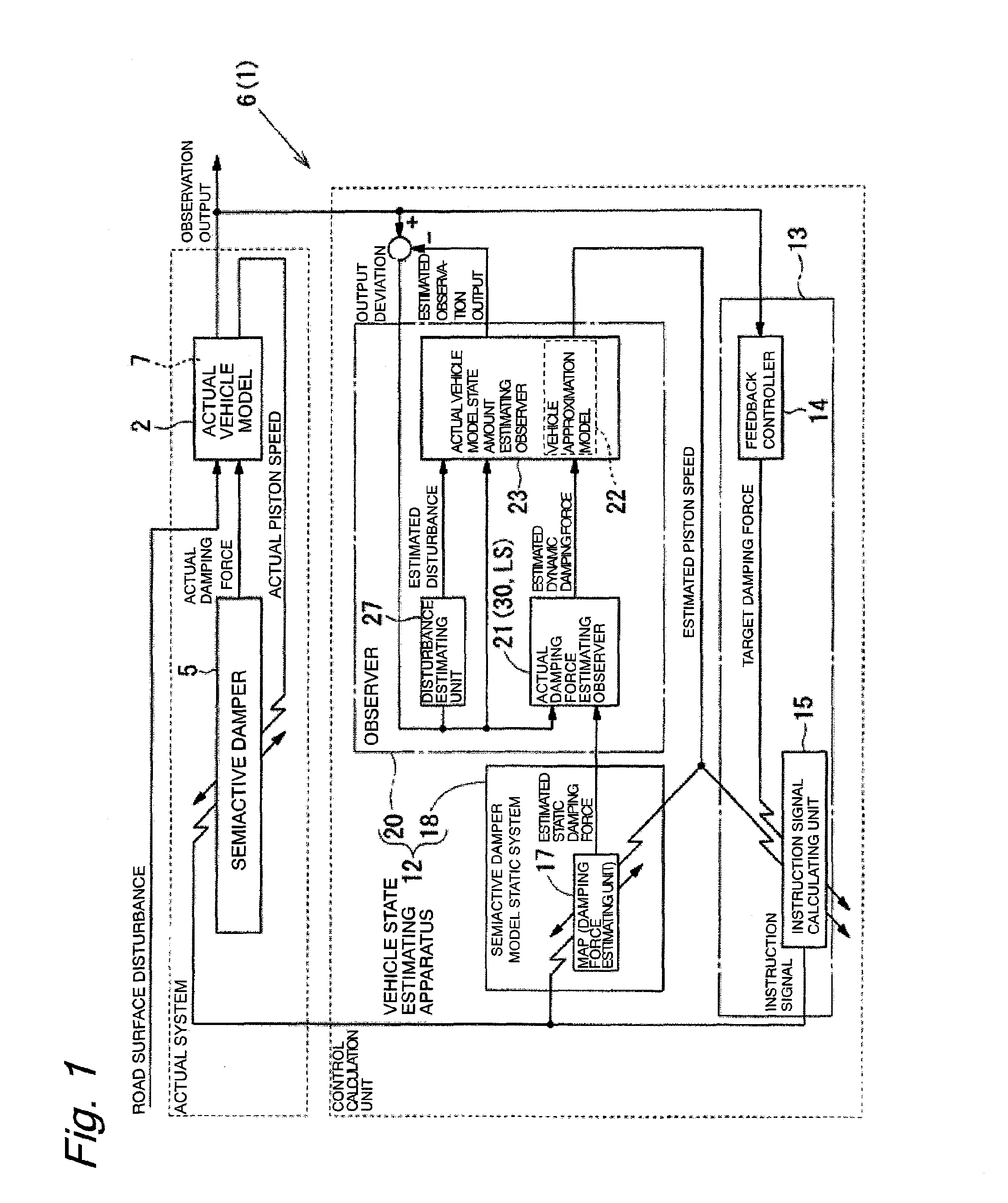
[0025]Referring to FIGS. 1 to 5, the semiactive suspension system 1 of the first embodiment of the present invention is used by being mounted on a vehicle (hereinafter also referred to as “actual vehicle model”) 2 which receives inputs of a road surface disturbance and an actual damping force (actual control force). The semiactive suspension system 1 generally comprises a variable damping force (control force) semiactive damper 5 (control suspension) and a suspension control apparatus 6. The semiactive damper 5 is operable to generate variable damping force (control force) and is disposed between a vehicle body 3 (sprung side) and a wheel 4 (unsprung side) of the vehicle 2. The suspension control apparatus 6 is operable to send an instruction signal to the semiactive damper 5. In the present embodiment, the vehicle 2 ha...


PUM


Abstract

A first observer gain of an actual damping force estimating observer 21 calculates a dynamic characteristic compensating signal, and a second observer gain of an actual vehicle model state amount estimating observer 23 calculates a vehicle model compensating signal, from an output deviation corresponding to a difference between a sprung speed (observation output) provided from a vehicle 2 and an estimated sprung speed (estimated observation output) provided from a vehicle approximation model of the actual vehicle model state amount estimating observer 23. The dynamic characteristic compensating signal is input into a dynamic characteristic providing unit of the actual vehicle model state amount estimating observer 23, and is used for adjustment of the setting of the dynamic characteristic providing unit. Therefore, it is possible to curb time lag occurrence in a control, and thereby perform a vibration control with improved accuracy.

Description

BACKGROUND OF THE INVENTION[0001]The present invention relates to a vehicle state estimating apparatus, a suspension control apparatus and a suspension system for use in a vibration control of a vehicle.[0002]For example, in a suspension control apparatus and a suspension system for use in a vibration control of a vehicle, an observer may be used for estimation of a motion state of the vehicle. Generally, such estimation of a motion state of a vehicle by an observer requires creation of a linear approximation model of the vehicle. In particular, the linear approximation model should have detectability, and an estimated control force input into the vehicle approximation model should be the same as an actual control force input into an actual vehicle. Unsatisfaction with these conditions may result in reduced estimation accuracy or impossibility of estimation.[0003]However, if a suspension control apparatus and a suspension system employ a control suspension which generates variable c...

Claims


Application Information

Patent Timeline
Patent Type & Authority Applications(United States)
IPC IPC(8): B60G17/018
CPCB60G17/0182B60G2400/202B60G2500/10B60G2800/916B60G2600/184B60G2600/1873B60G2600/182B60G17/00B60G17/015G01B21/00
Inventor ITAGAKI, NORIAKIICHIMARU, NOBUYUKIKOBAYASHI, TAKAHIDEGANKAI, TATSUYAFUKAO, TAKANORI
Owner HITACHI AUTOMOTIVE SYST LTD
Why Eureka
Try Eureka