Gun with mounted sighting device

Active Publication Date: 2010-03-11
CRIMSON TRACE
View PDF31 Cites 54 Cited by
  • Summary
  • Abstract
  • Description
  • Claims
  • Application Information

AI Technical Summary

Problems solved by technology

A problem associated with trigger-guard mounted laser sights is that trigger guards are complex, three-dimensional shapes with non-uniform cross-sections and it is difficult to mount, align and use the laser light.
When the laser sight is in this position the gun is difficult or impossible to holster and the gun / laser sight usually requires two hands to operate because one hand is required to hold the gun and another to turn the laser off and turn.

Method used


Image

  • Gun with mounted sighting device
  • Gun with mounted sighting device
  • Gun with mounted sighting device

Examples


Embodiment Construction

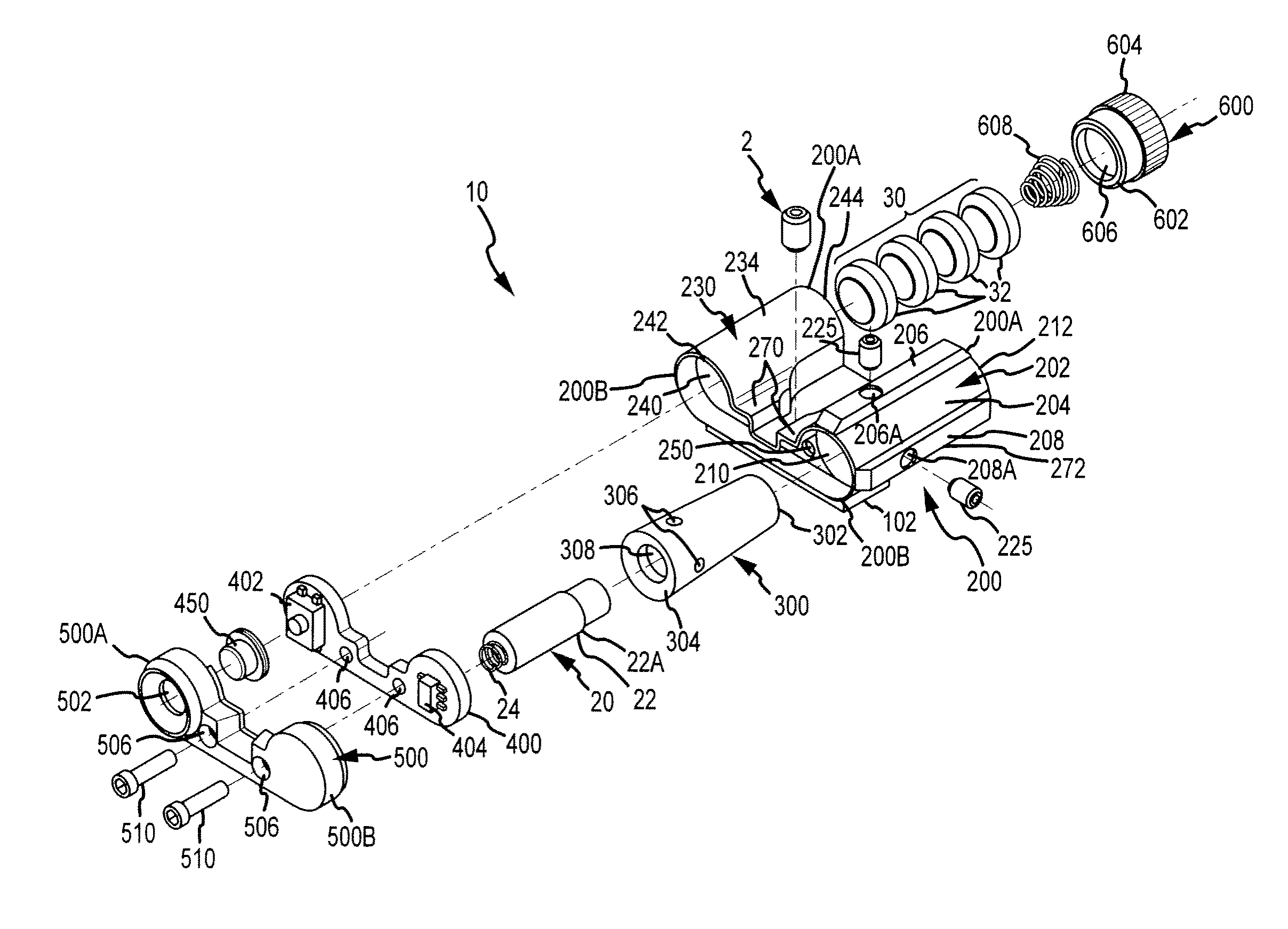
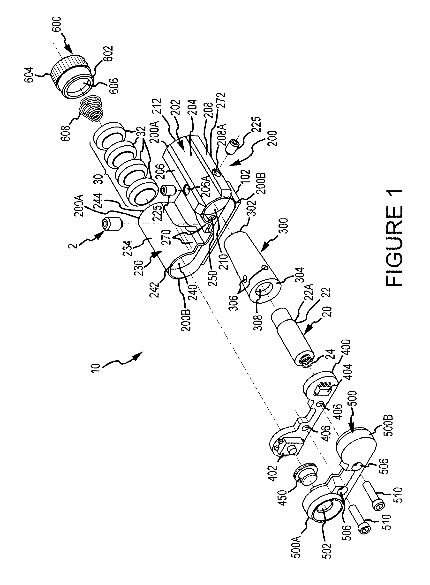
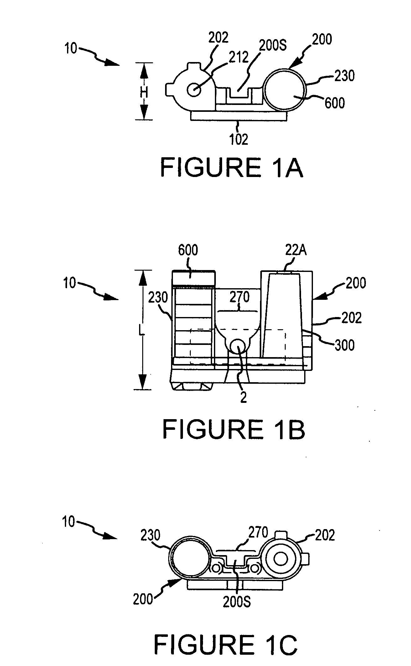
[0029]Turning now to the drawings where the purpose is to describe a preferred embodiment of the invention and not to limit same, FIGS. 1-11 show a preferred embodiment of a device 10 according to the invention. Device 10 as shown is a laser sight, but could be any structure that includes one or more light sources and one or more power sources connectable to the light source(s) and that can be mounted to a gun in the manner described herein.

[0030]Preferably, device 10 is configured to be mounted in a slot formed in the top surface of a gun, wherein device 10 provides a lighting source and preferably still allows a user to mechanically sight the gun. The slot (best seen in FIGS. 9 and 13) 2010 is known to those skilled in the art (if the slot is on the top surface of the gun it preferably extends the entire width of the top surface), and in one embodiment (for a Glock 19 pistol) is 1″ wide and 0.080″ deep. Device 10 could also be mounted to the top, rear portion or side, rear portion...


PUM


Abstract

A sighting device is mountable to a gun. The device includes a light source (preferably a laser), a power source connectable to the light source and a mount attachable to the gun so that the laser is juxtaposed either the top surface of the gun or a side surface of the gun. In one embodiment, the sighting device includes a bottom rail mountable in a slot on the gun, wherein the slot is preferably positioned on the top surface of the gun. The sighting device may also include a mechanical sight that functions as the rear mechanical sight on the gun and / or a secondary light source.

Description

FIELD OF THE INVENTION[0001]The present invention relates to a light-emitting sighting device, particularly a laser that is externally mountable on a weapon, the weapon preferably being a gun.BACKGROUND OF THE INVENTION[0002]It is known to utilize a light beam, such as a laser beam, as a sighting aid for weapons, particularly guns. Lasers are the preferred means of generating light beams for weapon sighting because they have comparatively high intensity and can be focused into a narrow beam with a very small divergence angle so they produce a small, bright spot on a target. The laser projects a narrow beam of light in a direction generally parallel to the gun's bore. When the light beam and bore are properly aligned, the bullet (or other projectile) will hit on or very close to the location of the light beam projected on a target.[0003]As used herein, “laser” includes any form of laser light source, and the term “laser sight” refers to a light emitting module or assembly that projec...

Claims


Application Information

Patent Timeline
IPC IPC(8): F41G1/00
CPCF41G1/35F41G11/003F41G1/36
Inventor MOORE, LARRY E.MOORE, AARON
Owner CRIMSON TRACE
Why Eureka
Try Eureka