Fin, thermal module, and method for assembling the same

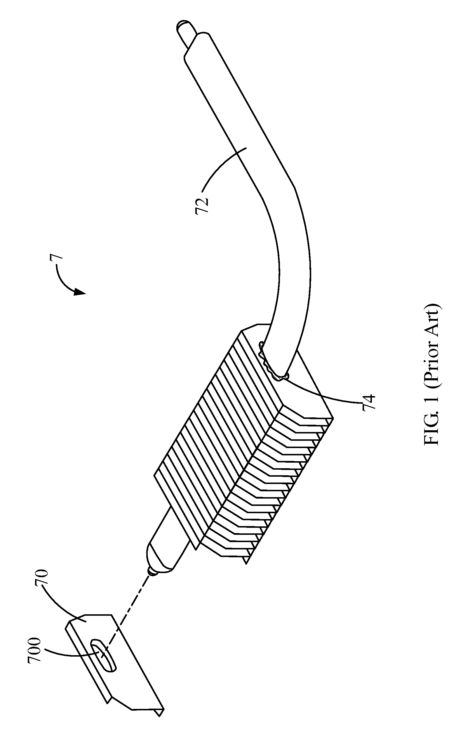
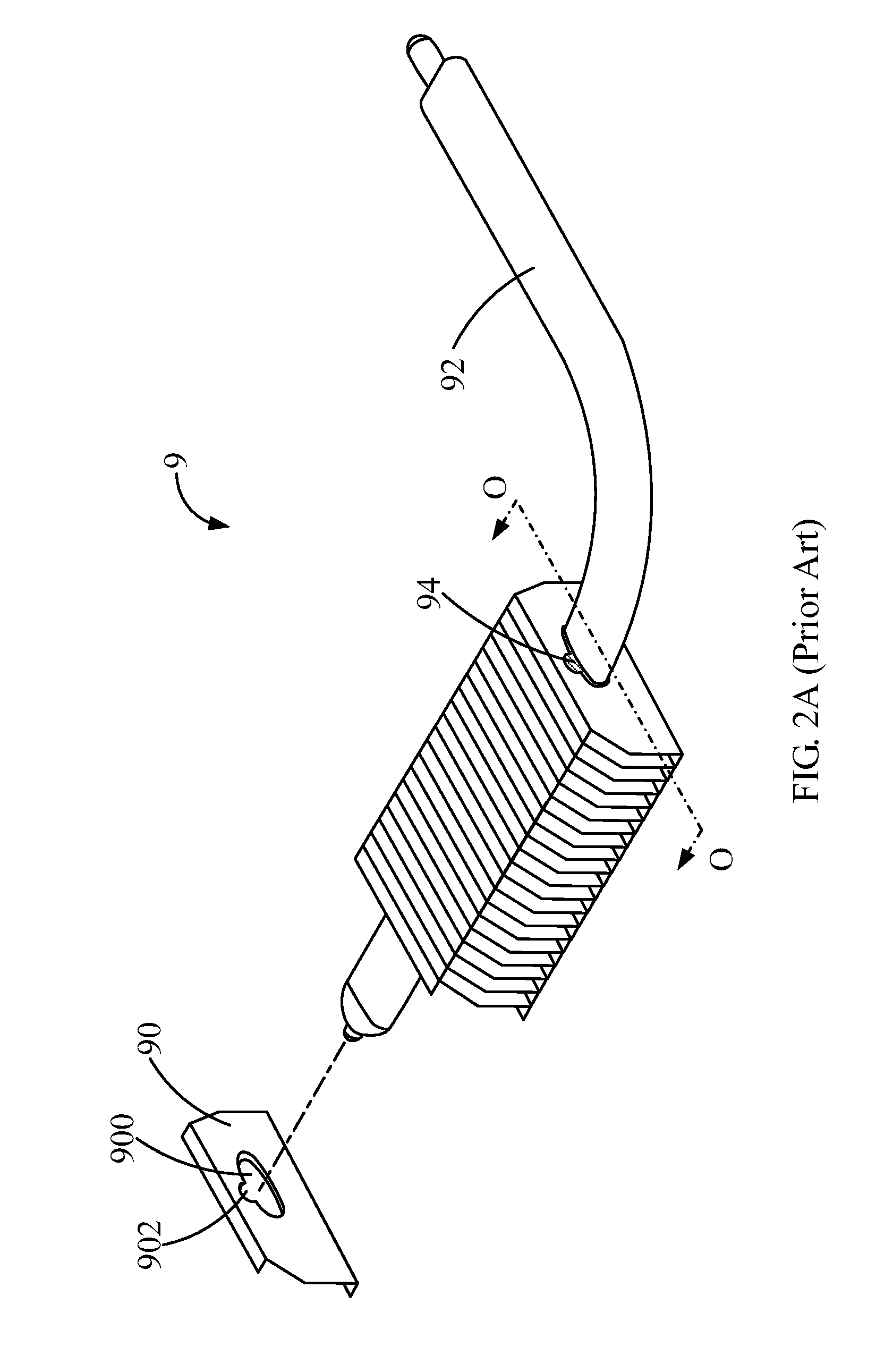
a cooling fin and thermal module technology, applied in the direction of tubular elements, metal-working apparatus, lighting and heating apparatus, etc., can solve the problems of high heat flux of heat dissipation, waste of solder paste b>74/b>, and additional labor, so as to improve the prior art and improve the quality of soldering and heat transfer performan

Inactive Publication Date: 2010-03-11
PEGATRON
View PDF2 Cites 8 Cited by
  • Summary
  • Abstract
  • Description
  • Claims
  • Application Information

AI Technical Summary

Benefits of technology

[0012]One objective of this invention is to provide a cooling fin and a method for assembling the thermal module. Particularly, the invention can uniformly spread the solder material to the clearance between the heat pipe and the fins of the thermal module. The soldering quality and the heat transfer performance can be well improved, thus to improve the prior art.

Problems solved by technology

For manufacturing light, slim, and powerful electronic device, a plurality of electronic elements is assembled on a circuit board with a limited area, which results in a high heat flux of heat dissipation.
Thus, additional labor is needed, and the solder paste 74 is wasted.
Further, the distribution of the solder paste 74 is non-uniform, deteriorating the heat dissipation.
In addition, the non-uniform distribution of the solder paste 94 may also deteriorate the heat dissipation.

Method used


Image

  • Fin, thermal module, and method for assembling the same
  • Fin, thermal module, and method for assembling the same
  • Fin, thermal module, and method for assembling the same

Examples


Embodiment Construction

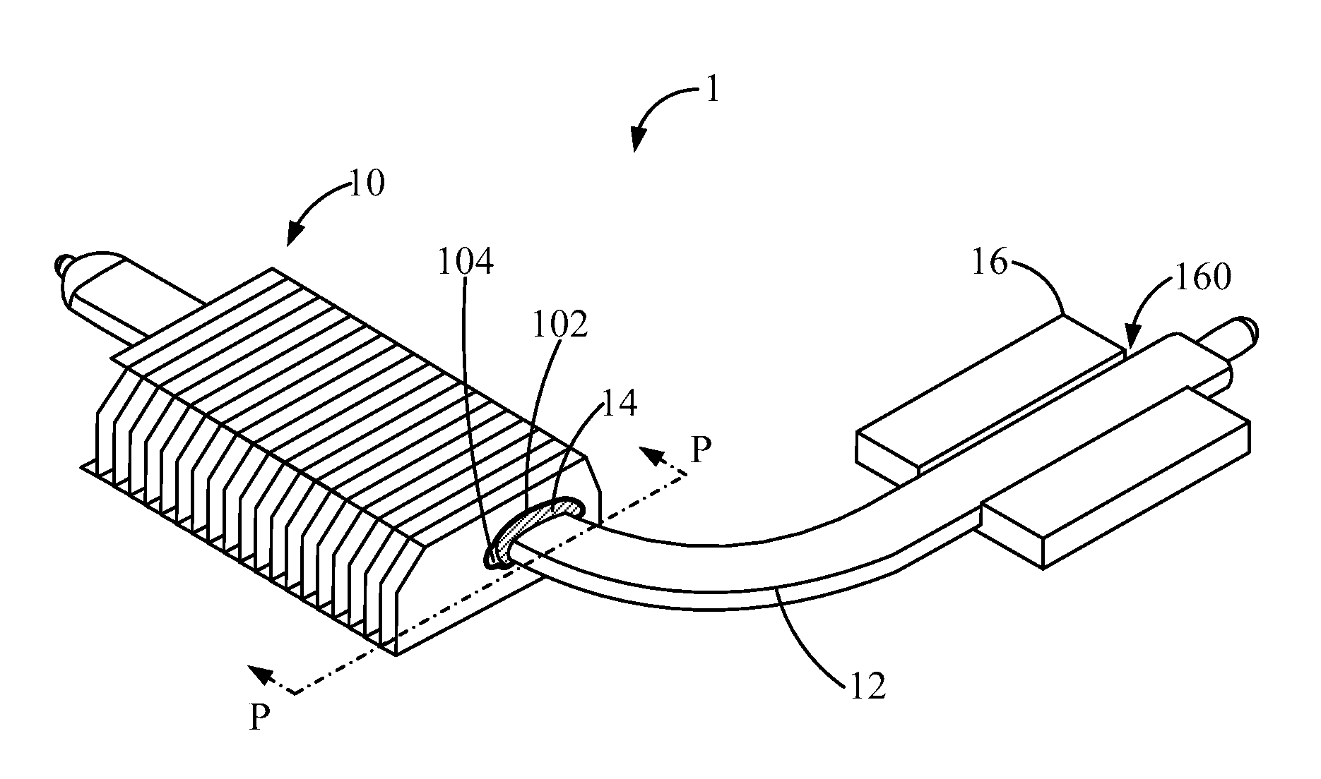
[0029]This invention provides a cooling fin, a thermal module including the cooling fin, and a method for assembling the thermal module.

[0030]According to one embodiment of the invention, the cooling fin can be combined with a heat pipe and a joint material, thus to form the thermal module. FIGS. 3A to 3B are schematic diagrams showing a fin according to one embodiment of the invention. Please refer to FIGS. 3A to 3C.

[0031]In FIGS. 3A to 3C, a main body 100 of a cooling fin 10 is flat, and the main body 100 has a through hole 102 and an feeding hole 104. The through hole 102 can be used for the heat pipe (not shown) to pass through. The feeding hole 104 communicates with the through hole 102. When the cooling fin 10 is combined with the heat pipe, the feeding hole 104 is above the through hole 102, and the joint material (not shown) is injected into the feeding hole 104 to fill a clearance between the heat pipe and the inner wall of the through hole 102. In addition, the through hol...


PUM

PropertyMeasurementUnit
angleaaaaaaaaaa
angleaaaaaaaaaa
angleaaaaaaaaaa

Abstract

This invention provides a method for assembling the thermal module. According to the invention, the fin can be combined with a heat pipe and a joint material to form the thermal module. The fin includes a main body having a through hole and an feeding hole communicating with each other. The heat pipe passes through the through hole. The joint material is injected into the feeding hole to fill a clearance between the heat pipe and the inner wall of the through hole. In addition, when the fin is combined with the heat pipe, the feeding hole is above the through hole, the joint material flows downward along the clearance, and the clearance gradually narrows along a flowing direction of the joint material.

Description

CROSS-REFERENCE TO RELATED APPLICATIONS[0001]This Non-provisional application claims priority under 35 U.S.C. §119(a) on Patent Application No(s). 097134173 filed in Taiwan, Republic of China on Sep. 5, 2008, the entire contents of which are hereby incorporated by reference.BACKGROUND OF THE INVENTION[0002]1. Field of the Invention[0003]The invention relates to a cooling fin, a thermal module including the cooling fin, and a method for assembling the thermal module.[0004]2. Description of the Related Art[0005]In past, only a central processing unit needs a thermal module to keep an operating temperature and stability of the central processing unit. With improvement of operating performance of other electronic elements, such as a graphic chip, a north bridge chip, a south bridge chip, a light-emitting diode and so on, the thermal module becomes more and more important for preserving stability of the electronic elements and the electronic devices having the electronic elements.[0006]F...

Claims


Application Information

Patent Timeline
Patent Type & Authority Applications(United States)
IPC IPC(8): F28D15/04F28F7/00B21D53/08
CPCF28D15/02F28F1/30Y10T29/49373F28F2275/04Y10T29/4935F28F2275/025
Inventor CHANG, YU WEICHUNG, CHAO TSAI
Owner PEGATRON
Why Eureka
Try Eureka