Child vehicle restraint system

a child restraint and child technology, applied in the field of child restraint systems, can solve the problem that the rest of the impact energy cannot rotate the child restraint as much, and achieve the effect of minimizing the risk of misuse and improving the crash behaviour of the child restrain

Inactive Publication Date: 2010-03-11
HTS HANS TORGERSEN & SONN AS
View PDF10 Cites 22 Cited by
  • Summary
  • Abstract
  • Description
  • Claims
  • Application Information

AI Technical Summary

Benefits of technology

[0008]The object of the present invention is to provide a solution which improves crash behaviour of the child restraint, and which offers an easy installation of the child safety seat in the vehicle, at the same time as minimizing the risk for misuse.
[0011]A child seat is releasable connected to the base by appropriate means. In order to minimize the rotation of the child restraint during a collision, the base of the child restraint is provided with an impact absorbing mechanism in the form of at least one ISOFIX connector and at least one blocker element, where the blocker element in an extracted position of the ISOFIX connector abuts against and locks the ISOFIX connector in this position under normal utilization of the child restraint. If the vehicle is involved in a crash from behind, where the vehicle, due to the crash, is exposed to sudden deceleration, then the blocker element will be forced out of abutment with the ISOFIX connector, thereby allowing the ISOFIX connector to slide into the base. This will result in the child restraint, after the blocker element has been brought out of abutment with the ISOFIX connector, moving towards the vehicle seat, whereafter the child restraint will begin to rotate. Since the impact energy from the collision has partly been absorbed in the process of bringing the blocker element out of abutment with the ISOFIX connector, the remaining impact energy will not be able to rotate the child restraint as much, as if not the energy has been absorbed. Consequently, the rotation of the child restraint is reduced.
[0012]In a preferred embodiment of the present invention the child restraint system comprises two ISOFIX connectors, where the ISOFIX connectors are slidably arranged within voids in the base. These voids are arranged with a given distance between each other, being placed towards the ends of the base, when seen in the longitudinal direction of the base (i.e. when the base is secured into the vehicle seat in its normal position of use). This will stabilize the child restraint in a sideway direction.
[0014]The voids may be provided on their inside with an arrangement that will prevent the ISOFIX connectors being pulled completely out of the voids. In its simplest form, this arrangement may involve both the voids and ISOFIX connectors being provided with a flange, where the abutment of the flanges will prevent further movement of the ISOFIX connectors.
[0020]In this position a stud on the blocker element will protrude through the recess and into the voids, where the ISOFIX connectors are arranged. The stud will then be abutting against one end of the ISOFIX connectors, thereby “locking” the ISOFIX connectors in this position. The portion of the stud that abuts the ISOFIX connectors has a curved surface. This will result in the stud being forced out of abutment with the ISOFIX connectors if it is subjected to a force, for instance from a vehicle collision. In this case the ISOFIX connectors will be pushed towards the curved portion of the stud; if this force exceeds a certain value, the stud will be forced to rotate around the pivot connection and eventually the ISOFIX connectors will be able to slide into the voids. This will result in the child restraint moving towards the vehicle seat, and first after that the ISOFIX connectors have reached their innermost position in the voids, will the child restraint rotate around the anchorage points in the vehicle seat. However, as some of the impact energy has been absorbed during the process of pushing the stud out of engagement with the ISOFIX connectors, the remaining impact energy will not be able to rotate the child restraint as much as if the impact energy has not been absorbed. This will reduce the rotation of the child restraint.

Problems solved by technology

Since the impact energy from the collision has partly been absorbed in the process of bringing the blocker element out of abutment with the ISOFIX connector, the remaining impact energy will not be able to rotate the child restraint as much, as if not the energy has been absorbed.

Method used


Image

  • Child vehicle restraint system
  • Child vehicle restraint system
  • Child vehicle restraint system

Examples


Embodiment Construction

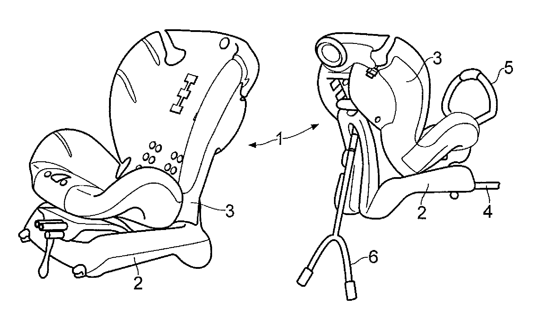
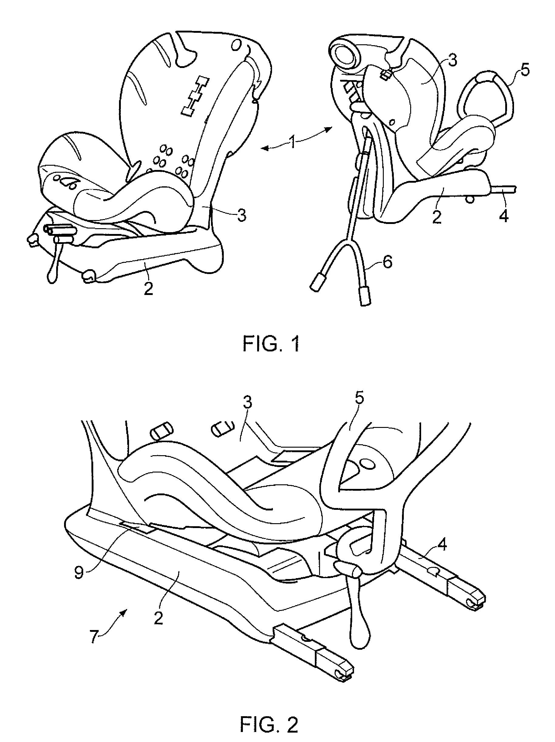
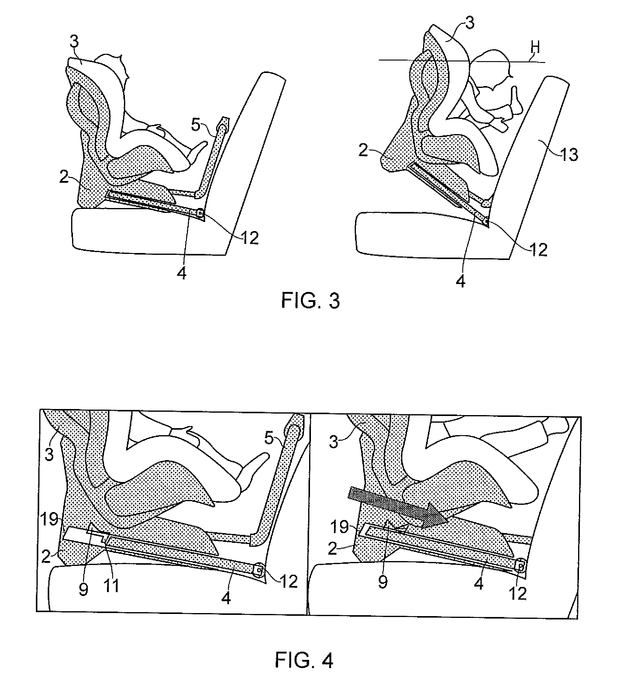
[0031]FIG. 1 shows a child restraint system 1 according to the present invention, where the child restraint is intended to be used both in a forward-facing position (shown on the left side in FIG. 1) and a rearward-facing position (shown on the right side in FIG. 1). The child restraint system 1 comprises a base 2 and a child seat 3 that is releasable connected to the base 2. The base 2 is provided with two ISOFIX connectors 4, such that the base 2 can be connected to standard anchorage points 12 (see FIG. 3) arranged in a vehicle seat 13. The ISOFIX connector 4 is in the form of a bar and is slidably arranged within a void 8 in the base 3. A seat support 5 is connected to the base 3, where the seat support 5 through a tightening and releasing mechanism can be brought in or out of abutment with a back portion of the vehicle seat 13. This will fit the child restraint securely in the vehicle seat when the child restraint is used with the ISOFIX connectors 4. In order to further secure...


PUM


Abstract

The present invention relates to a child restraint system (1) with a base (2) having a lower surface resting on a sitting portion of a vehicle, where the base (2) through ISOFIX latching means is engaged with anchorage means (12) in the vehicle seat (13), thereby providing a pivot connection between the base (2) and the anchorage means (12). Through an energy absorbing mechanism (7) impact energy can be absorbed, thus reducing the degree of rotation of the child restraint (1).

Description

FIELD OF THE INVENTION[0001]The present invention relates to a child restraint system for use in a vehicle with seat assembly equipped with standard anchorage units. The child restraint system may also be used in a vehicle using a safety belt or other securing means. More particularly the present invention relates to an energy absorbing child restraint system.BACKGROUND[0002]Most child restraint systems are currently designed to be fitted in a vehicle seat and secured to it by using a vehicle's adult lap and diagonal seat belt, or sometimes just the lap belt. However, vehicle seats, seat belts and their anchorages vary greatly between different models of vehicles; the seats have different shapes, the seat belts may be shorter or longer, the position of the anchor points differs etc. All these factors make it virtually impossible to make a child restraint system that fits in all vehicles and this sometimes make it complicated or even impossible to fit the child restraint system corre...

Claims


Application Information

Patent Timeline
Patent Type & Authority Applications(United States)
IPC IPC(8): B60N2/427B60N2/42B60N2/28B60N2/90
CPCB60N2/2824B60N2/2845B60N2/2893B60N2/2881B60N2/2884B60N2/2863
Inventor VERTEGAAL, HENDRICUS JOHANNES
Owner HTS HANS TORGERSEN & SONN AS
Why Eureka
Try Eureka