Inductor and inductor coil

a technology of inductor coil and inductor, which is applied in the direction of transformer/inductance details, fixed inductances, and inductances, etc., can solve the problem that the typical inductor b>10/b> cannot meet the need of reducing the size of electronic devices

Inactive Publication Date: 2010-03-11
HON HAI PRECISION IND CO LTD
View PDF9 Cites 4 Cited by
  • Summary
  • Abstract
  • Description
  • Claims
  • Application Information

AI Technical Summary

Problems solved by technology

Thus, the typical inductor 10 cannot satisfy the need of reducing the size of electronic devices.

Method used


Image

  • Inductor and inductor coil
  • Inductor and inductor coil
  • Inductor and inductor coil

Examples


Embodiment Construction

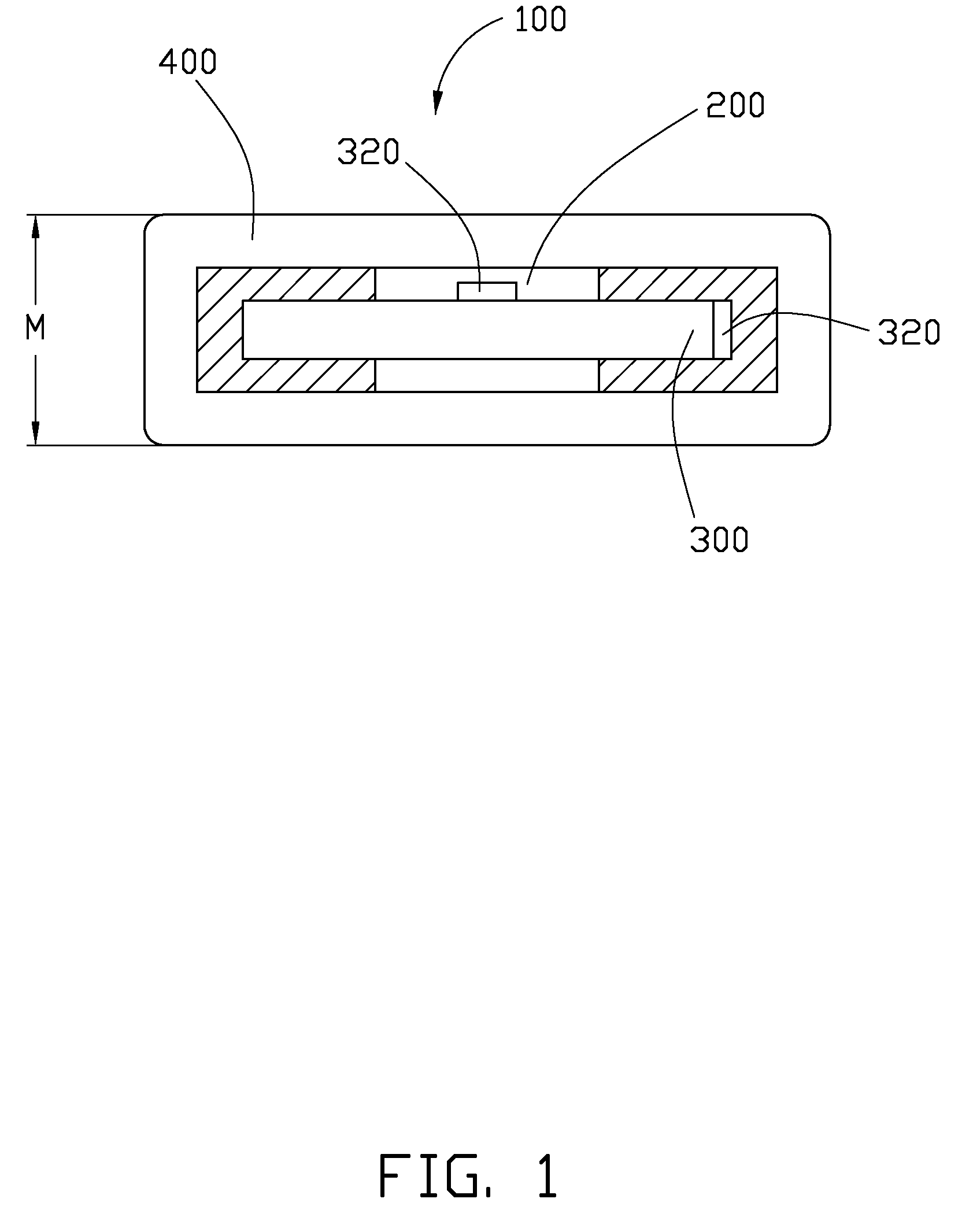
[0009]Referring to FIG. 1, an embodiment of an inductor 100 includes a ferromagnetic core 200, an inductor coil 300, and a holder 400.

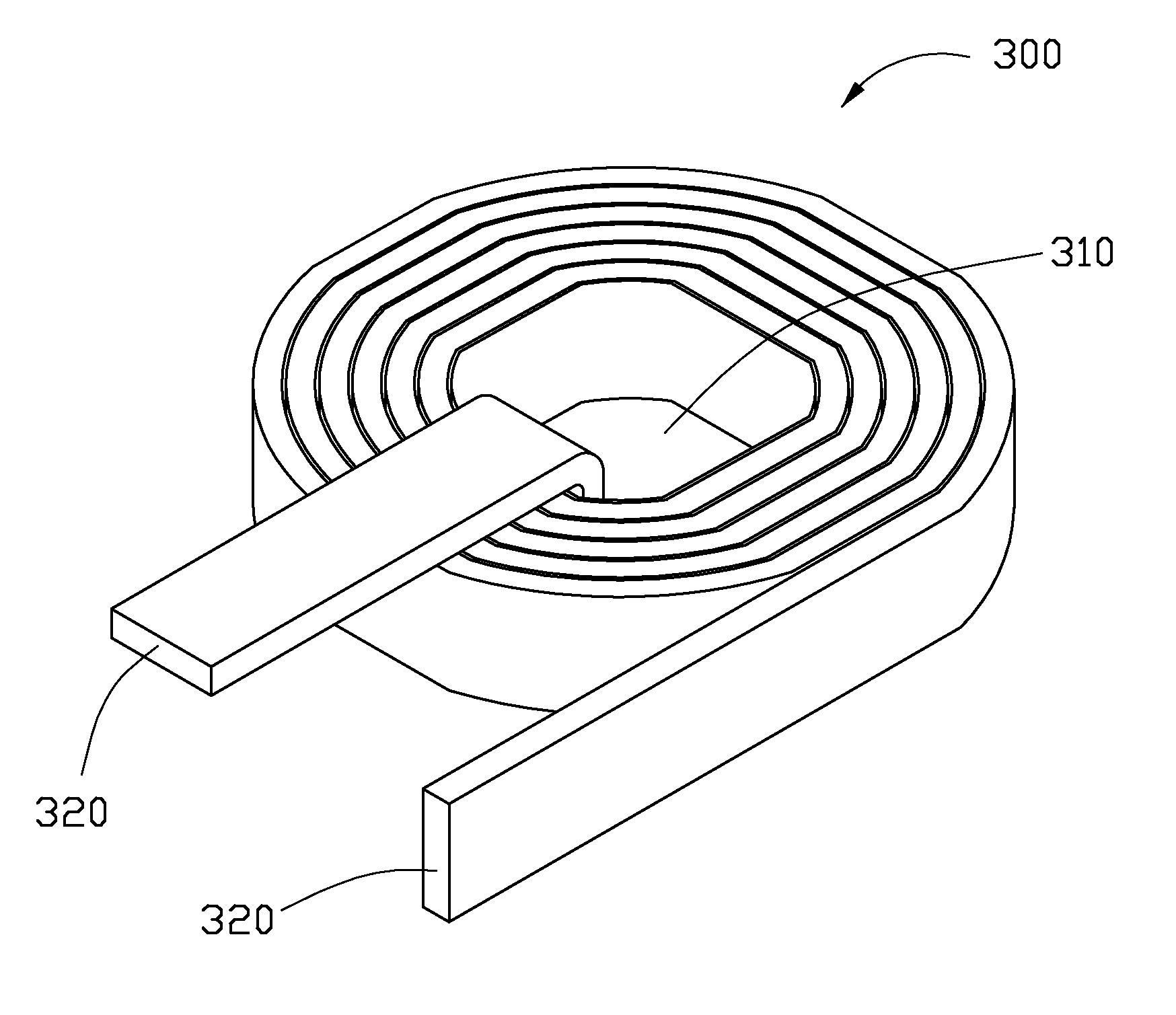
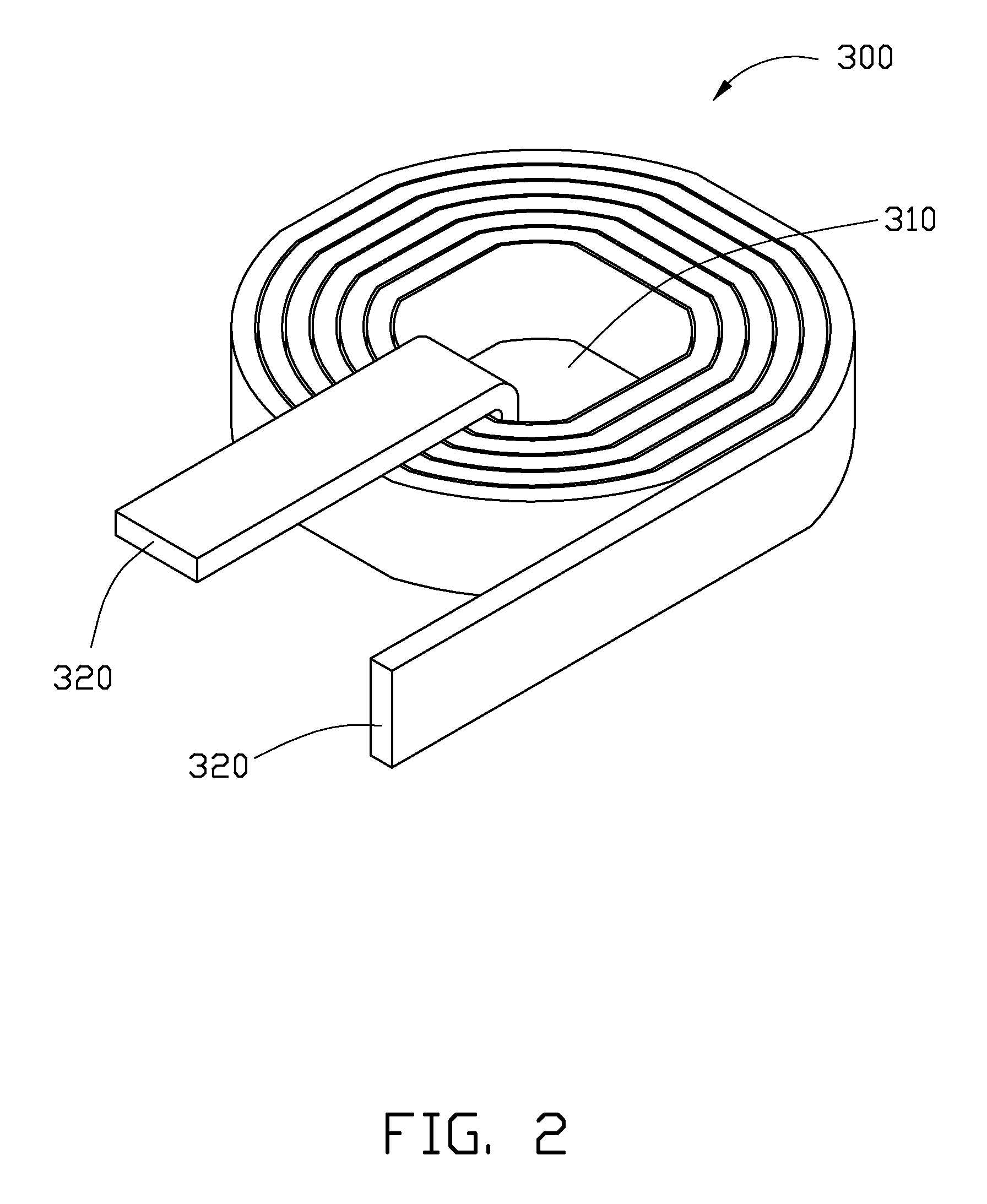
[0010]Referring to FIG. 2, the inductor coil 300 is a long flat conductor, made of a conductive material such as copper, and is coiled to form one or more loops. The inductor coil 300 may be wrapped with insulation tape. The inductor coil 300 defines a through hole 310 surrounded by an innermost loop of the one or more loops to fit about the ferromagnetic core 200. The ferromagnetic core 200 with the inductor coil 300 is arranged in the holder 400. Two ends 320 of the inductor coil 300 protrude out of the holder 400 for connecting to peripheral circuits.

[0011]Since the inductor 100 employs a long flat conductor coiled to form an annular member, the length M of the inductor 100 is small. Therefore, the inductor coil 300 can satisfy the need of reducing the size of electronic devices employing inductors.

[0012]The working theory of the inductor 100 can b...


PUM

PropertyMeasurementUnit
ferromagneticaaaaaaaaaa
lengthaaaaaaaaaa
sizeaaaaaaaaaa

Abstract

An inductor includes a ferromagnetic core, an inductor coil, and a holder. The inductor coil is coiled to form one or more loops around a center. The inductor coil defines a through hole surrounded by an innermost loop to fit about the ferromagnetic core. The holder is configured for holding the ferromagnetic core with the inductor coil. Two ends of the inductor coil protrude out of the holder.

Description

BACKGROUND[0001]1. Field of the Invention[0002]The present invention relates to an inductor and an inductor coil.[0003]2. Description of Related Art[0004]Inductors are passive electrical components widely used in electronic devices. Referring to FIG. 3, a typical inductor 10 includes a ferromagnetic core 20, an inductor coil 30, and a holder 40. The inductor coil 30 is helical shaped, and wrapped around the ferromagnetic core 20. The ferromagnetic core 20 is arranged in the holder 40. Two ends 32 of the inductor coil 30 protrude out of the holder 20 for connecting to peripheral circuits. However, the typical inductor 10 has a great length L because the inductor coil 30 is very long. Thus, the typical inductor 10 cannot satisfy the need of reducing the size of electronic devices.[0005]What is needed is to provide an inductor that has a small length.BRIEF DESCRIPTION OF THE DRAWINGS[0006]FIG. 1 is a plan, schematic view of an embodiment of an inductor having an inductor coil.[0007]FIG...

Claims


Application Information

Patent Timeline
Patent Type & Authority Applications(United States)
IPC IPC(8): H01F27/30
CPCH01F17/045H01F27/2847H01F2027/2857H01F2017/046H01F27/2852
Inventor TAI, FANG-TALIN, CHEN-HSIANG
Owner HON HAI PRECISION IND CO LTD
Why Eureka
Try Eureka