Communication interface apparatus for an electrical distribution panel, and system and electrical distribution panel including the same

a technology of communication interface and electrical distribution panel, which is applied in the direction of instruments, audible signalling systems, signalling systems, etc., can solve the problems of inability to provide trip protection and inability to provide warning

Active Publication Date: 2010-03-11
EATON INTELLIGENT POWER LIMITED
View PDF14 Cites 41 Cited by
  • Summary
  • Abstract
  • Description
  • Claims
  • Application Information

AI Technical Summary

Problems solved by technology

When the trip coil of known circuit breakers fails to an open circuit condition, such circuit breakers a

Method used


Image

  • Communication interface apparatus for an electrical distribution panel, and system and electrical distribution panel including the same
  • Communication interface apparatus for an electrical distribution panel, and system and electrical distribution panel including the same
  • Communication interface apparatus for an electrical distribution panel, and system and electrical distribution panel including the same

Examples


example 1

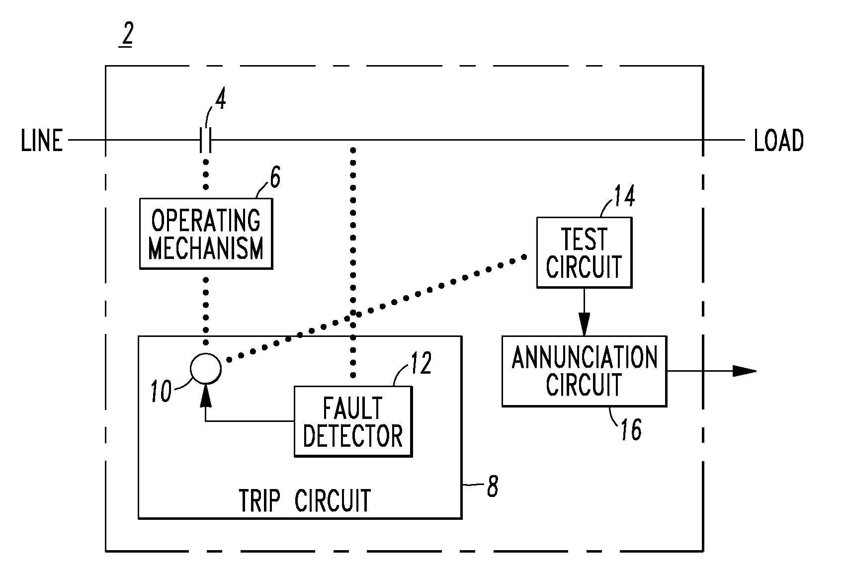
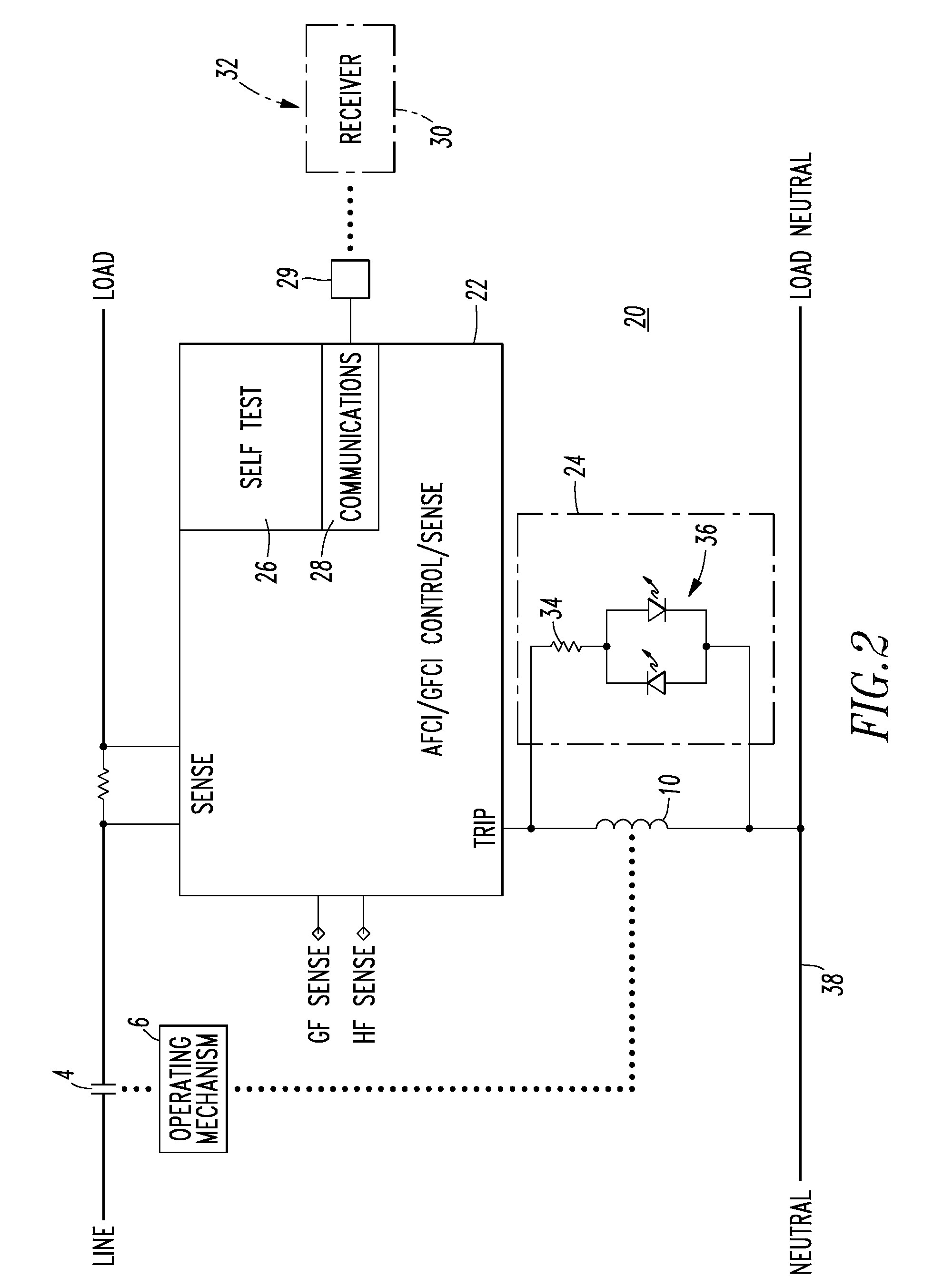
[0037]FIG. 2 shows an arc fault / ground fault circuit breaker 20 including the separable contacts 4, the operating mechanism 6 and the trip coil 10 of FIG. 1, along with an AFCI / GFCI control / sense circuit 22, an open coil sense and indication circuit 24, a self test circuit 26 and a communications circuit 28. It will be appreciated that these circuits 22,24,26,28 can be combined and / or can be implemented by any suitable number of analog, digital and / or processor-based circuits. The example circuits 22,24,26,28 cooperatively detect and communicate circuit breaker failure states through output 29 (e.g., transmitter) to a receiver 30 (shown in phantom line drawing) in, at, on or near an electrical distribution panel 32 (shown in phantom line drawing). One or both of the open coil sense and indication circuit 24 and the self test circuit 26 detect a failure of the trip coil 10. One or both of the open coil sense and indication circuit 24 and the communications circuit 28 provide a corres...

example 2

[0038]In this example, the trip coil 10 includes a voltage. One or both of the open coil sense and indication circuit 24 and the self test circuit 26 can be a test circuit structured to sense the voltage of the trip coil 10, determine if that voltage is greater than a predetermined value, and responsively determine an open circuit condition of the trip coil 10.

[0039]The circuit 24, as shown, includes the series combination of a resistor 34 and a bi-directional light emitting diode (LED) 36 (i.e., the LED is illuminated by current flowing in either direction through the resistor 34). As will be described, during the open circuit condition of the trip coil 10, a predetermined current flows through that series combination. In the absence of that open circuit condition, the voltage of the trip coil 10 is insufficient to illuminate the bi-directional LED 36.

[0040]The detection of the open trip coil 10 of the circuit breaker 20 is possible since the operating power for the AFCI / GFCI contr...

example 3

[0042]For example and without limitation, the resistance of the trip coil 10 is normally about 20 ohms and with the nominal current through the AFCI / GFCI control / sense circuit 22 of about 12 mA, the voltage across the trip coil 10 is, thus, normally about 0.2 V. The example resistance of resistor 34 is about 5 kΩ (with a 3 W power rating to make this circuit highly reliable) and the voltage thereacross is, thus, about 50 V when the trip coil 10 is open. If the trip coil 10 is open, then the current through resistor 34 provides the power to operate the circuit 22 and, also, lights the LED 36 to visually indicate the trip coil failure. Hence, the open coil status sensor provided by the circuit 24 can preferably be sized to provide an alternate path in order to keep the electronics of the AFCI / GFCI control / sense circuit 22 operational and / or to illuminate the LED 36 for failure indication.


PUM


Abstract

A system includes a number of electrical switching apparatus having separable contacts, an operating mechanism structured to open and close the separable contacts, a trip mechanism cooperating with the operating mechanism to trip open the separable contacts, a test circuit structured to test the trip mechanism and determine a failure to protect condition thereof, and a communication circuit structured to communicate the failure to protect condition. The system also includes an electrical distribution panel having a housing housing the number of electrical switching apparatus, and a communication interface structured to receive the failure to protect condition from the communication circuit and annunciate the failure to protect condition.

Description

[0001]This application is a continuation-in-part of application Ser. No. 12 / 206,194, filed Sep. 8, 2008, and entitled “Electrical Switching Apparatus Including A Trip Coil Open Circuit Test Circuit And System Including The Same”.BACKGROUND[0002]1. Field[0003]The disclosed concept pertains generally to electrical switching apparatus, such as circuit interrupters, and, more particularly, to electrical distribution panels including such electrical switching apparatus. The disclosed concept also pertains to systems including an electrical distribution panel. The disclosed concept further pertains to communication interfaces for electrical distribution panels.[0004]2. Background Information[0005]Electrical switching apparatus include, for example, circuit switching devices; circuit interrupters, such as circuit breakers; network protectors; contactors; motor starters; motor controllers; and other load controllers.[0006]Ground fault circuit interrupters (GFCIs) include ground fault circui...

Claims


Application Information

Patent Timeline
IPC IPC(8): G08B21/00
CPCG01R31/3272H02H3/335G01R31/3275
Inventor HETZMANNSEDER, ENGELBERTMURPHY, WILLIAM J.ELMS, ROBERT T.
Owner EATON INTELLIGENT POWER LIMITED
Why Eureka
Try Eureka