Phase compensation for multi-stimulus controller

a multi-stimulus controller and phase compensation technology, applied in the field of multi-stimulus sensor controllers, can solve problems such as reducing the efficiency of sense signal processing

Active Publication Date: 2010-03-11
APPLE INC
View PDF19 Cites 139 Cited by
  • Summary
  • Abstract
  • Description
  • Claims
  • Application Information

AI Technical Summary

Benefits of technology

[0004]In view of the foregoing, a multi-stimulus controller for a multi-touch sensor is formed on a single integrated circuit (single-chip) to include a transmit oscillator, a transmit signal section that generates a plurality of drive signals based on a frequency of the transmit oscillator, a plurality of transmit channels that transmit the drive signals simultaneously to drive the multi-touch sensor, a receive channel that receives a sense signal resulting from the driving of the multi-touch sensor, a receive oscillator, and a demodulation se

Problems solved by technology

While these systems offer some advantages, conventional multi-stim systems can cause difficulties.
For example, in a typical multi-stim system, different driv

Method used


Image

  • Phase compensation for multi-stimulus controller
  • Phase compensation for multi-stimulus controller
  • Phase compensation for multi-stimulus controller

Examples


Embodiment Construction

[0019]In the following description of preferred embodiments, reference is made to the accompanying drawings which form a part hereof, and in which it is shown by way of illustration specific embodiments in which the invention can be practiced. It is to be understood that other embodiments can be used and structural changes can be made without departing from the scope of the embodiments of this invention.

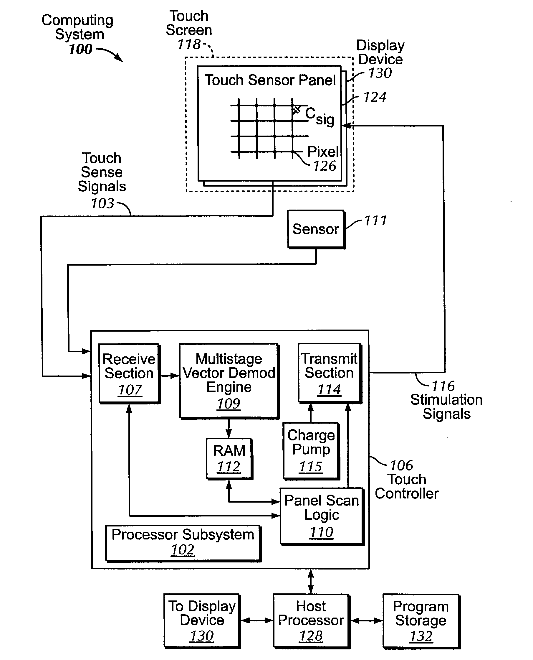
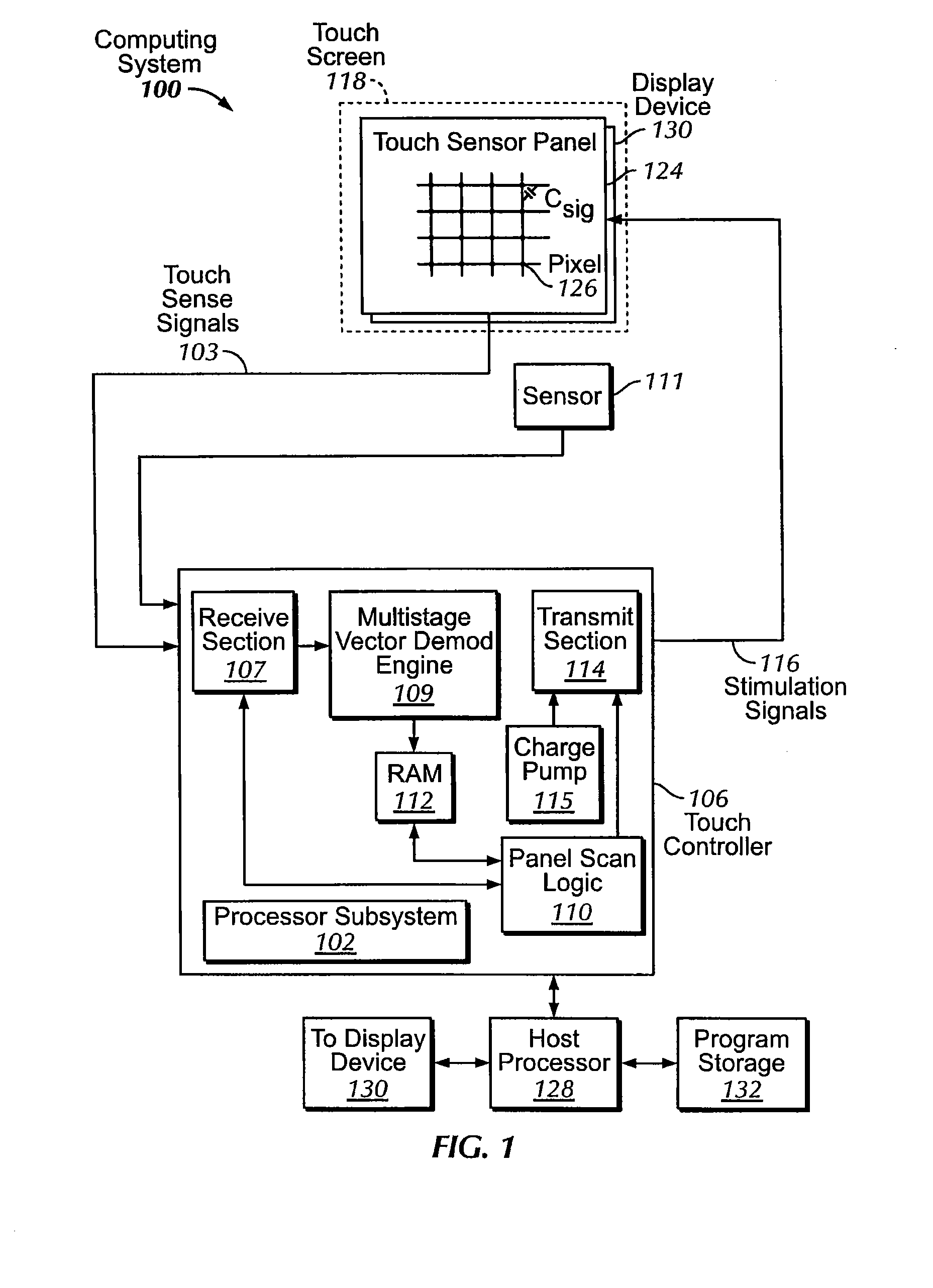
[0020]This relates to compensating for phase delay in multi-stimulus touch controllers. When stimulating a single sense line with multiple drive signals, multiple component signals can be generated in the sense line. The component signals form a composite sense signal, which can be received and used in, for example, a demodulation process for obtaining measurement data contained in the component signals. However, the individual component signals can have different phase delays caused by, for example, different signal path lengths. It can be difficult to compensate for the individual ...


PUM


Abstract

Determining a compensated phase matrix for a multi-stimulus demodulation process is provided. A first drive line of a multi-stimulus sensing system is selected, and a stimulation signal is transmitted on the selected drive line. A channel gain resulting from the stimulation signal is measured from a received sense signal resulting from the stimulation signal. The measured channel gain is compared with a known channel gain to obtain an individual phase compensation for the selected drive line. A compensated phase matrix is formed of the individual phase compensation values for multiple drive lines.

Description

FIELD OF THE INVENTION[0001]This relates generally to controllers for multi-stimulus sensors, and in particular, to compensating for phase delay in multi-stimulus touch controllers.BACKGROUND OF THE INVENTION[0002]Many types of input devices are presently available for performing operations in a computing system, such as buttons or keys, mice, trackballs, joysticks, touch sensor panels, touch screens and the like. Touch screens, in particular, are becoming increasingly popular because of their ease and versatility of operation as well as their declining price. Touch screens can include a touch sensor panel, which can be a clear panel with a touch-sensitive surface, and a display device such as a liquid crystal display (LCD) that can be positioned partially or fully behind the panel so that the touch-sensitive surface can cover at least a portion of the viewable area of the display device. Touch screens can allow a user to perform various functions by touching the touch sensor panel ...

Claims


Application Information

Patent Timeline
IPC IPC(8): G06F3/041
CPCG06F3/0416G06F3/041G06F3/044G06F3/04166G06F3/0446H03K17/96G06F2203/04104
Inventor KRAH, CHRISTOPH H.
Owner APPLE INC
Why Eureka
Try Eureka