Integrated beamformer/modem architecture

a beamformer and modem technology, applied in the field of wireless communication transceivers and modems, can solve the problems of increasing hardware costs, increasing the cost of beamform functions, and increasing the incremental cost of adding capability to modems, so as to increase computational complexity, reduce computational rates, and increase processing demands

Active Publication Date: 2007-08-21
LIONRA TECH LTD
View PDF20 Cites 173 Cited by
  • Summary
  • Abstract
  • Description
  • Claims
  • Application Information

AI Technical Summary

Benefits of technology

[0021]In accordance with the present invention, a modulator/demodulator (modem) architecture is presented for TDMA and FDMA applications. In particular, a transceiver configured to simultaneously communicate with multiple users, such as a base station transceiver, employs a phased-array antenna capable of generating a steerable, directed antenna beam for communication with other devices. Rather than implementing the beamforming phase and amplitude control of the antenna elements in the front-end circuitry, the signals from each antenna element are independently processed all the way down to the individual baseband channel level, and digital beamforming is performed at baseband. While this approach would suggest significantly higher processing demands due to the separate processing for each antenna element, the transceiver of the present invention is implemented using a symmetrical processing structure, leveraging the relationship of increasing computational complexity with decreasing computational rate from IF to baseband processing.

Problems solved by technology

This forces the computationally intense beamforming to take place at a much higher sampling rate, resulting in more mathematical operations per second, and corresponding increased hardware cost.
In addition to the resulting inability to support advanced demodulation techniques with this architecture, the cost of the beamforming function is greater as a stand-alone function, compared to the incremental cost of adding the capability to a modem.
The largest cost-component of beamforming is the complex multiplication of each sample for each element with the beamforming weights.
Thus

Method used


Image

  • Integrated beamformer/modem architecture
  • Integrated beamformer/modem architecture
  • Integrated beamformer/modem architecture

Examples


Embodiment Construction

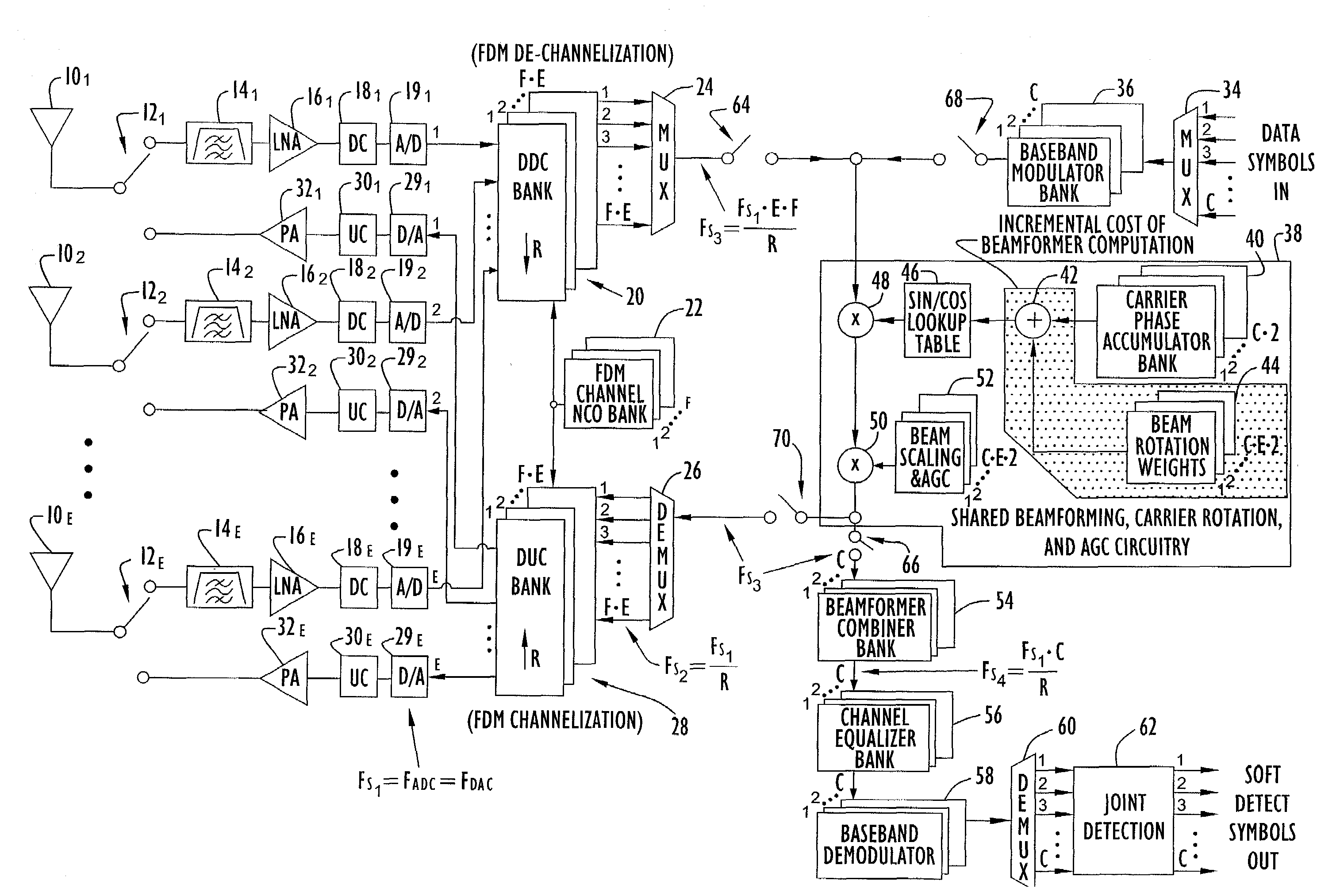
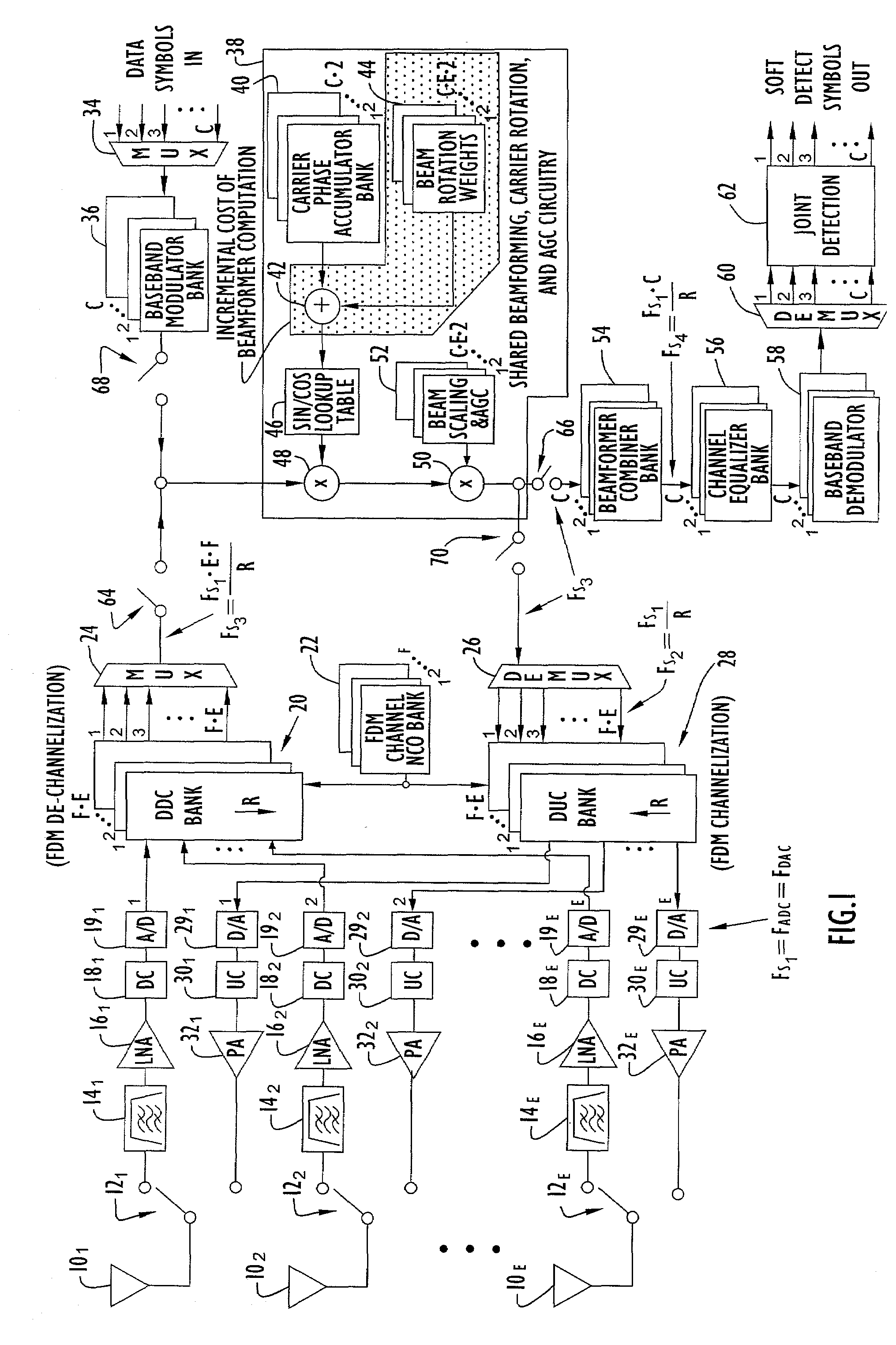
[0027]The following detailed explanations of FIGS. 1-3 and of the preferred embodiments reveal the methods and apparatus of the present invention. FIG. 1 is a generalized functional block diagram of an integrated beamformer / modem architecture in accordance with an exemplary embodiment of the present invention. The beamformer / modem architecture of the present invention can be employed in any communication device that transmits or receives signals from other communication devices. As used herein and in the claims, a “communication device” includes any device, mobile or stationary, that is capable of transmitting and / or receiving communication signals, including but not limited to: a handheld or body-mounted radio; any type of mobile or wireless telephone (e.g., analog cellular, digital cellular, PCS or satellite-based); a pager, beeper or PDA device; a radio or transceiver carried on, built into or embedded in a ground-based or airborne vehicle; any portable electronic device equipped...


PUM


Abstract

A transceiver employing a steerable phased-array antenna includes a modem architecture in which signals from each antenna element in the array are independently processed down to the individual baseband channel level, and digital beamforming is performed at baseband. The data rate reduction from IF to baseband permits parallel signal data from multiple antenna elements to be time multiplexed and serially processed at acceptable data rates at baseband with minimal modem hardware requirements. Both for transmit signal modulation and received signal demodulation, the computation of carrier tracking, automatic gain control (AGC)/power-control, and beamforming are shared by the same processing circuitry for all channels when performed at baseband. The resulting baseband circuitry is only incrementally larger than that required for carrier tracking and AGC alone, yet accomplishes independent beamforming for each antenna element on each user channel.

Description

CROSS REFERENCE TO RELATED APPLICATION[0001]This application claims priority from U.S. Provisional Patent Application Ser. No. 60 / 271,961 entitled “Integrated TDMA Beamformer / Modem Architecture,” filed Feb. 28, 2001. The disclosure of this provisional patent application is incorporated herein by reference in its entirety.BACKGROUND OF THE INVENTION[0002]1. Field of the Invention[0003]The present invention relates to wireless communication transceivers and modems and, more particularly, to the construction of a multi-frequency, multi-channel transceiver system such as might be used in a multi-user base station for terrestrial cellular or fixed-wireless applications.[0004]2. Description of the Related Art[0005]Directional antennas are widely used in a variety of communications systems to more efficiently transmit and receive radiated signals. Relative to an isotropic antenna, which transmits and receives signals equally in all directions, a directional antenna has an antenna gain patt...

Claims


Application Information

Patent Timeline
IPC IPC(8): H04B1/38H04L5/16H01Q3/26H01Q3/30H04B7/06H04B7/08
CPCH01Q3/26H01Q3/30H04B7/0617H04B7/086
Inventor BIERLY, SCOTTHARLACHER, MARCSMARRELLI, ROBERTWEINBERG, AARON
Owner LIONRA TECH LTD
Why Eureka
Try Eureka