Sensing circuit for capacitive touch panel

Active Publication Date: 2010-03-11
INNOLUX CORP
View PDF3 Cites 116 Cited by
  • Summary
  • Abstract
  • Description
  • Claims
  • Application Information

AI Technical Summary

Benefits of technology

[0011]A primary objective of the present invention is to provide a sensing circuit for a capacitive touch panel. By adding a path for a noise to pass through, the noise is differentially

Problems solved by technology

However, regardless if it is the capacitive touch panel 150 in FIG. 1 or the capacitive touch panel 250 in FIG. 2, there exists a problem that a noise affects the sensing signal.
For example, the noise is generated when a source bus of the liquid crystal display panel is driven to

Method used


Image

  • Sensing circuit for capacitive touch panel
  • Sensing circuit for capacitive touch panel
  • Sensing circuit for capacitive touch panel

Examples


first embodiment

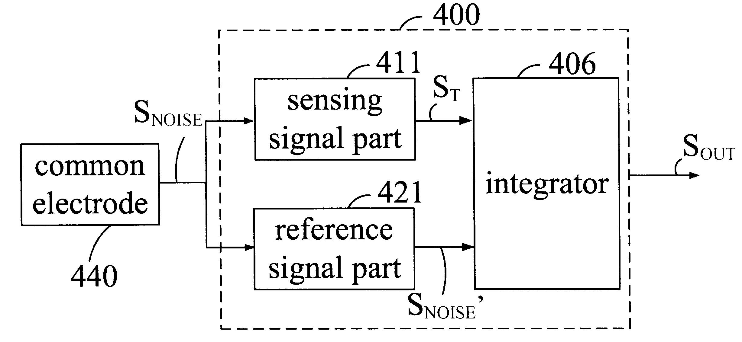
[0022]In order to be clearly understood, the following will describe differences between the prior arts and the present invention. Please refer to FIG. 5. FIG. 5 illustrates a circuit diagram shown in FIG. 4. This embodiment is a sensing circuit 500 utilized in a capacitive touch panel where scan lines are sequentially scanned from one direction to the other direction. A sensing signal part 511 comprises a sensing unit 512 and a sensing signal generating unit 514. A reference signal part 521 comprises a reference unit 522 and a reference signal generating unit 524.

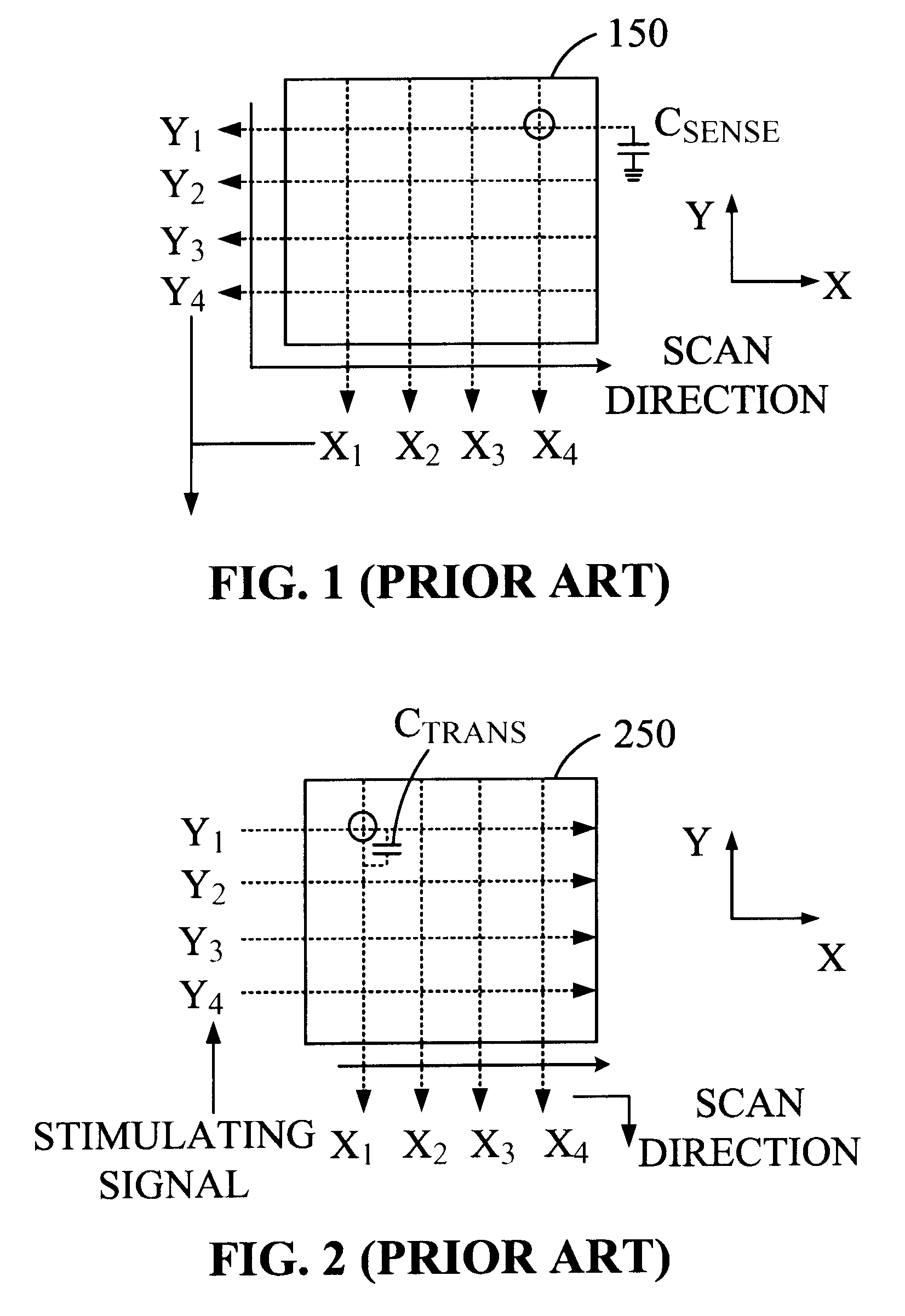
[0023]The sensing unit 512 has a sensing capacitance which is represented as CSENSE. When the capacitive touch panel is untouched, the sensing capacitance CSENSE of the sensing unit 512 is zero. When the capacitive touch panel is touched, the sensing capacitance CSENSE is not zero. In addition, the sensing unit 512 further has a parasitic capacitance. The parasitic capacitance is an equivalent capacitance between a common...

second embodiment

[0038]Please refer to FIG. 6. FIG. 6 illustrates a circuit diagram shown in FIG. 4. This embodiment is a sensing circuit 600 utilized in a capacitive touch panel where scan lines in only one direction are scanned and a stimulating signal is inputted to scan lines in the other direction. A sensing signal part 611 comprises a sensing unit 612 and a sensing signal generating unit 614. A reference signal part 621 comprises a reference unit 622 and a reference signal generating unit 624.

[0039]When the capacitive touch panel is touched, the sensing unit 612 has a sensing capacitance which is represented as CTRANS. A capacitance of the capacitive touch panel at an untouched condition, that is, the capacitance that the reference unit 622 simulates the capacitance of the capacitive touch panel at the untouched condition is represented as CTRANS′. In addition, the sensing unit 612 further has parasitic capacitances. The parasitic capacitances are equivalent capacitances between a common elec...


PUM


Abstract

A sensing circuit for a capacitive touch panel is disclosed. By adding a path for a noise to pass through, the noise is differentially processed through two paths which have the same electrical conditions with each other. The noise is then decreased significantly, and a sensing signal can be detected correctly.

Description

CROSS REFERENCE TO RELATED APPLICATION[0001]This application claims the benefit of U.S. Provisional Patent Application Ser. No. 61 / 095,214, filed Sep. 8, 2008.BACKGROUND OF THE INVENTION[0002]1. Field of the Invention[0003]The present invention generally relates to a sensing circuit, and more particularly to a sensing circuit for a capacitive touch panel.[0004]2. Description of Prior Art[0005]Applications of conventional touch panels are widely used, for example, mobile phones, touch screens for public information, automatic teller machines (ATMs) and so on. The intuitive operations of a touch panel can be substituted for the functions of a keyboard and a mouse; therefore, the touch panel is quite convenient in use.[0006]Please refer to FIG. 1 and FIG. 2. FIG. 1 and FIG. 2 illustrate two types of capacitive touch panels 150, 250 for detecting a touch position. In FIG. 1, the capacitive touch panel 150 comprises a plurality of sensing lines in the X-axis direction and in the Y-axis d...

Claims


Application Information

Patent Timeline
IPC IPC(8): G06F3/045
CPCG06F3/044G06F3/04182
Inventor WU, TSE-HUNG
Owner INNOLUX CORP
Why Eureka
Try Eureka