Graphics rendering system

a graphics and rendering system technology, applied in the field of computer graphics, can solve the problems of specifying a rendering order, a low degree of user control over the final onscreen, and the user cannot create graphics with a specified rendering order

Inactive Publication Date: 2010-03-11
AGENCY 9 AB
View PDF9 Cites 55 Cited by
  • Summary
  • Abstract
  • Description
  • Claims
  • Application Information

AI Technical Summary

Benefits of technology

[0006]The object of the present invention is therefore to provide a solution, which solves the above problems thus offers a graphics processing tool wherein the user can control the rendering order of a data structure which complies with an open standard.

Problems solved by technology

Of course, this is disadvantageous from a flexibility point-of-view.
However, neither of these standards specifies a rendering order.
Therefore, the standards provide a low degree of user control with respect to the final onscreen result.
Hence, a user cannot create graphics with a specified rendering order, and at the same time, work within the scope of existing open standards.
Moreover, even if the user sacrifice the open-standard compatibility, modifying the rendering algorithm to attain a specified result is a fairly complex task.

Method used


Image

  • Graphics rendering system
  • Graphics rendering system
  • Graphics rendering system

Examples


first embodiment

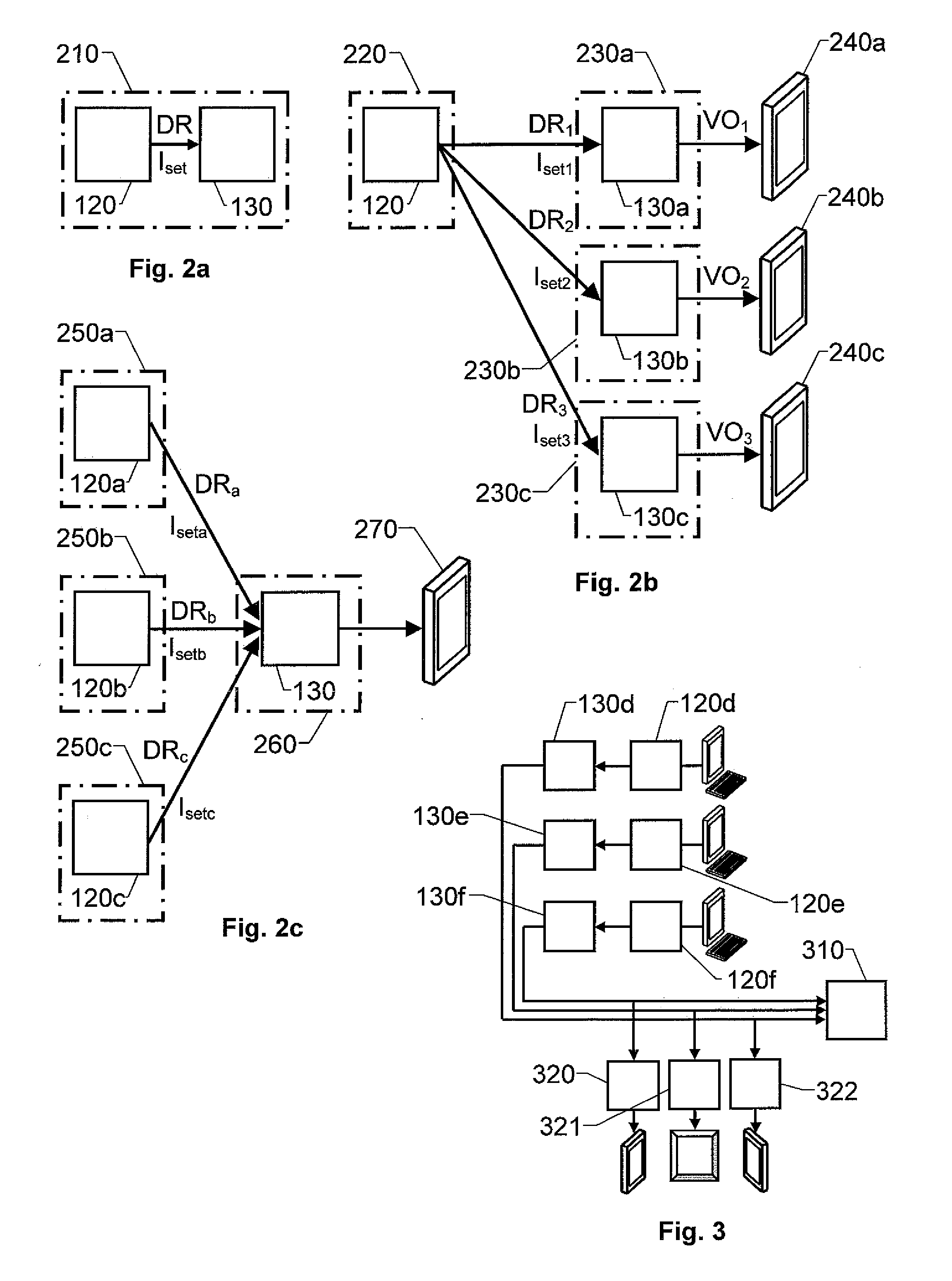
[0047]FIG. 2a illustrates a client- and server-module configuration according to the invention, wherein the client module 120 and the server module 130 are implemented in a common data-processing apparatus 210, e.g. a work station, a personal computer, a laptop, PDA, a smartphone or a mobile telephone. This implementation is suitable for a single-user environment.

second embodiment

[0048]FIG. 2b illustrates a client- and server-module configuration according to the invention. Here, the client module 120 is implemented in a first data-processing apparatus 220 and the server module 130 is implemented in second data-processing apparatuses 230a, 230b and 230c respectively. Alternatively, two or more of the data-processing apparatuses 230a, 230b and 230c may be represented by different processor cores of a single apparatus. In any case, the client module 120 is adapted to transfer a first set of data resources DR1 and a first instruction set Iset1 to a first server module 130a implemented in a primary data-processing apparatus 230a to produce a first visual output VO1; transfer a second set of data resources DR2 and a second instruction set Iset2 to a second server module 130b implemented in a secondary data-processing apparatus 230b to produce a second visual output VO2; and transfer a third set of data resources DR3 and a third instruction set Iset3 to a server m...

third embodiment

[0049]FIG. 2c illustrates a client- and server-module configuration according to the invention. Here, a number of client modules 120a, 120b and 120c are implemented in a respective data-processing apparatus 250a, 250b and 250c. Each client module 120a, 120b and 120c is adapted to transfer data resources DRa, DRb and DRc respectively and instructions Iseta, Isetb and Isetc respectively to a data-processing apparatus 260 implementing a common server module 130. This embodiment is desirable when a plurality of users shall cooperate to create a graphics environment in a comparatively powerful data-processing apparatus. The different data resources DRa, DRb and DRc respectively and instructions Iseta, Isetb and Isetc may either a common scene or different scenes in the graphics environment.

[0050]Naturally, according to the invention, various forms of combinations, or hybrids, between the embodiments described above with reference to FIGS. 2a, 2b and 2c are conceivable. For example, the p...


PUM


Abstract

A graphics processing solution wherein operator-generated commands concerning a data structure describing a graphics scene are received via an user interface associated with a client module. Based on the commands, the client module produces at least one set of data resources and at least one instruction set. Each resource in the set of data resources represents a given graphical content of the scene, and the instruction set describes interrelationships between these resources. The client module is adapted to transfer the data resources and instruction sets to a server module. The server module is associated with a memory means having at least one data area which each is adapted to store an amount of data relating to a given context of the scene. Each amount of data is organized as a set of data resources and an instruction set, which may have a different format than the data resources and instruction sets produced in the client module. The server module implements at least one rendering kernel configured to generate a visual output data based on the set of data resources and the instruction set. The visual output data represents a projection of the scene onto a two-dimensional graphics display and has a format adapted for presentation on the graphics display.

Description

THE BACKGROUND OF THE INVENTION AND PRIOR ART[0001]The present invention relates generally to rendering of computer graphics. More particularly the invention relates to a rendering system according to the preamble of claim 1 and a method according to claim 15. The invention also relates to a computer program according to claim 23 and a computer readable medium according to claim 24.[0002]Graphics rendering is the process of generating an image from a model by means of computer programs. The resulting image is a digital image, i.e. a two-dimensional data representation in the form of a finite set of digital values called picture elements, or pixels. The underlying model is a description of three-dimensional (3D) objects in a strictly defined data structure, for example represented by a scene graph. The data structure typically contains information regarding geometry, viewpoint, texture and lighting. The rendering process is effected as a last main step in the graphics pipeline in ord...

Claims


Application Information

Patent Timeline
Patent Type & Authority Applications(United States)
IPC IPC(8): G06T1/00G06T15/00
CPCG06T15/005
Inventor KARLSSON, TOMASWEDIN, LASSELINDBERGH, JOHAN
Owner AGENCY 9 AB
Why Eureka
Try Eureka