
Method and apparatus for determining reporting period of channel quality information in multi-carrier wireless system

a multi-carrier wireless and channel quality technology, applied in the field of method and apparatus for determining the reporting period of channel quality indicators, can solve the problems of hardly feeding back channel quality indicators and becoming more sever

Active Publication Date: 2010-03-11
ELECTRONICS & TELECOMM RES INST
View PDF6 Cites 24 Cited by
  • Summary
  • Abstract
  • Description
  • Claims
  • Application Information

AI Technical Summary

Benefits of technology

The present invention provides a method and apparatus for determining the feedback period of a channel quality indicator in a multi-carrier wireless system. The technical effects of the invention include allowing a mobile station to use a weighted channel quality indicator based on the average channel gain rather than the mobile station's channel gain, determining a different feedback period for the channel quality indicator for each mobile station based on its channel state and moving velocity, and improving the feedback success probability for a mobile station with a good channel state. These technical effects enhance the efficiency and reliability of wireless communication systems.

Problems solved by technology

However, when the same threshold value is assigned to all users and the feedback of channel state information is made according to a result of comparison of an estimated channel gain and one threshold value, there is a problem that a mobile station of highest reception power level, e.g., a mobile station closes to a base station, can easily feed back channel quality indicator while a mobile station of low reception power level, e.g., a mobile station located far away from a base station, can hardly feed back the channel quality indicator.
As a result, according to the conventional approach, there occurs a problem of fairness on user capacity within the same cell, which can become more severe as a reception power level difference of users becomes bigger.

Method used


Image

  • Method and apparatus for determining reporting period of channel quality information in multi-carrier wireless system
  • Method and apparatus for determining reporting period of channel quality information in multi-carrier wireless system
  • Method and apparatus for determining reporting period of channel quality information in multi-carrier wireless system

Examples


first embodiment

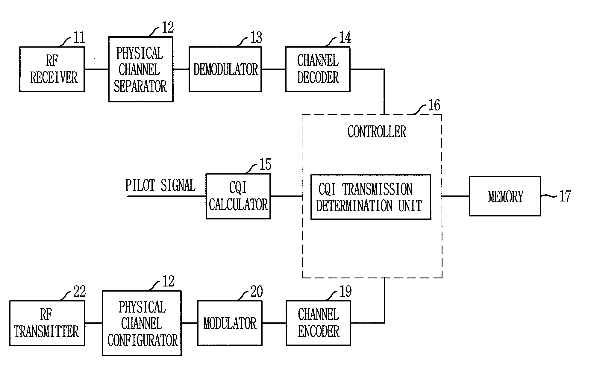
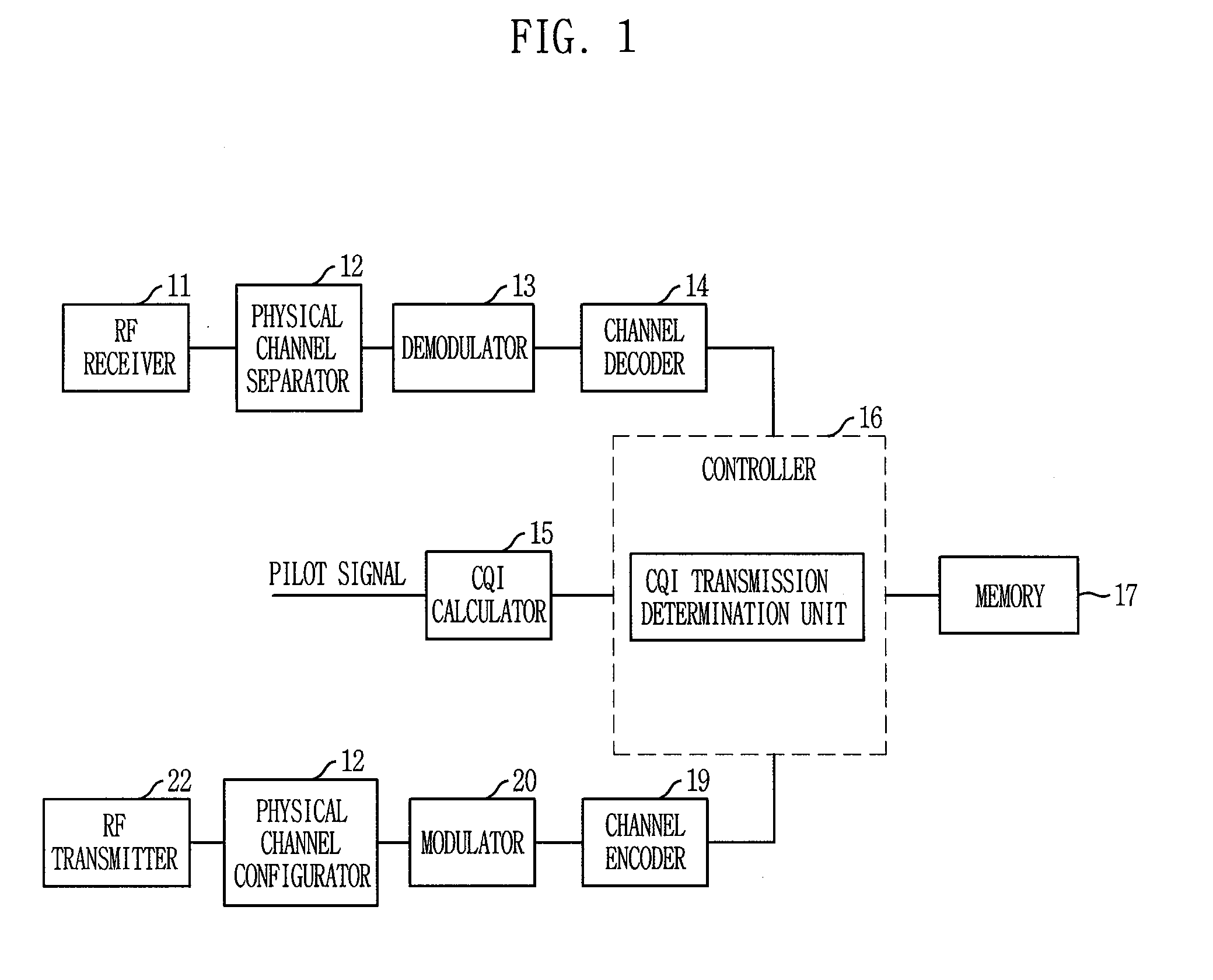
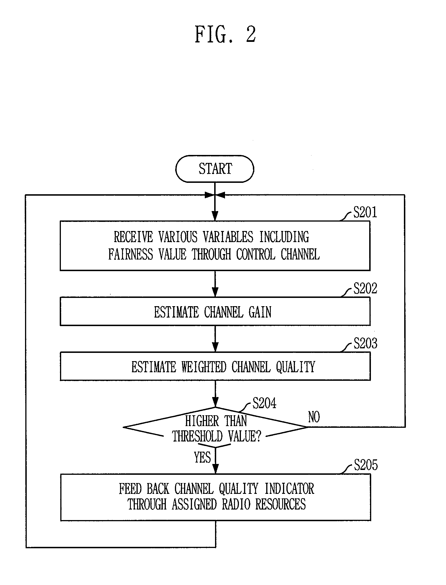
[0042]Hereinafter, description is made for the first embodiment in which the controller of a mobile station determines whether or not channel quality indicator is transmitted by using weighted channel quality in order to feed back the channel quality indicator. Equation 1 as below is for defining a weight Wk used for an arbitrary Kth user.

Wk=[1E[hk2]]f,Eq.1

[0043]Where |hk|2 denotes a channel gain of the Kth user, f a factor determining a fairness value, and E[.] statistical expectation value operation. That is, a weight is estimated by obtaining a value through dividing 1 by a statistical expectation value as to a channel gain, and then raising the obtained value to the power of a factor determining fairness information.

[0044]Furthermore, the weight channel quality for each mobile station is obtained by multiplying a weight value by a channel gain (Wk*|hk|2), and the mobile station implements feedback of channel quality indicator only if the weight channel quality satisfies the cond...

second embodiment

[0060]FIG. 3 is a flowchart describing a method for determining a feedback period for feedback of channel quality indicator in accordance with the present invention.

[0061]In the second embodiment of the present invention, a feedback period of channel quality indicator is differently determined according to a channel state.

[0062]First, a mobile station receives and stores in a table of the memory feedback period information according to a channel state from a base station through a control channel at step S301. In other words, the base station differently determines and stores a feedback period for feedback of channel state information according to a channel state level having a predetermined range through tests or simulations, and transmits the feedback period according to the channel state through the control channel to the mobile station.

[0063]Next, the mobile station estimates channel quality indicator by using a pilot signal received from the base station at step S302, and check...

third embodiment

[0066]the present invention differently determines a feedback period of channel quality indicator according to a moving velocity of a mobile station.

[0067]First, a mobile station receives and stores in a table of the memory feedback period information according to its own moving velocity through a control channel from a base station. In other words, the base station differently determines and stores a feedback period for feedbacks of channel quality indicator according to a moving velocity level of a mobile station, wherein the moving velocity level has a predetermined range, and transmits to the mobile station the feedback period according to the moving velocity of the mobile station through the control channel.

[0068]Next, the mobile station measures its own moving velocity based on position information measured by a GPS receiver which is a global positioning system, and checks from a table stored in the memory a feedback period according to the measured moving velocity of the mobi...


PUM


Abstract

Provided are a method and an apparatus for determining a reporting period of channel quality indicator. The method includes the steps of: a) estimating a channel gain through a channel received from a base station; b) calculating a weight by using a variable for determining a fairness value and the estimated channel gain, and estimating weight channel quality to the estimated channel gain by using the calculated weight; c) comparing the estimated weight channel quality and a threshold value; and d) feeding back estimated channel quality indicator by using wireless resources assigned for the channel quality indicator feedback only in case that the weight channel quality is higher than the threshold value.

Description

TECHNICAL FIELD[0001]The present invention relates to a method and an apparatus for determining a reporting period for providing channel quality indicator; and, more particularly, to a method and an apparatus for determining a reporting period, i.e., a feedback period, for providing channel quality indicator in order to feed back the channel quality indicator such as a channel quality indicator (CQI) in a multi-carrier wireless system such as an Orthogonal Frequency Division Multiple Access (OFDMA) communication system.[0002]This work was supported by the IT R&D program of MIC / IITA [2006-S-001-01, “Development of Adaptive Radio Access and Transmission Technologies for 4th Generation Mobile Communications”].BACKGROUND ART[0003]Even though the wireless communications were initially developed to provide voice services, technologies for providing data services have been developing according to rapid technological improvements. Furthermore, as the demands for data transmissions and the n...

Claims


Application Information

Patent Timeline
Patent Type & Authority Applications(United States)
IPC IPC(8): H04J1/16
CPCH04B7/0632H04L1/0027H04L1/0026H04B7/0647
Inventor SEO, BANGWONLEE, HEESOOCHUNG, HYUN-KYUKIM, DONGWOOLEE, IN-HO
Owner ELECTRONICS & TELECOMM RES INST
Learn More