Handover method with mobile relay station

a mobile relay station and handover technology, applied in the direction of electrical equipment, wireless commuication services, network topologies, etc., can solve the problems of long time to enter the network, long breakage of communication, and congestion in random access channels, so as to reduce communication breakage and effectively use radio resources

Inactive Publication Date: 2010-03-11
ELECTRONICS & TELECOMM RES INST
View PDF10 Cites 76 Cited by
  • Summary
  • Abstract
  • Description
  • Claims
  • Application Information

AI Technical Summary

Benefits of technology

[0034]According to an embodiment of the present invention, since handovers of a mobile relay station (MRS) and mobile stations (MSs) which are attached to the MRS are initiated by the MRS or base stations (BSs), it is possible to reduce breaks of communication to effectively use radio resources.Best Mode
[0035]According to an aspect of the present invention, there is provided a handover method for a Mobile Relay Station (MRS), the handover method including transmitting a handover request message to a serving Base Station (BS), wherein the handover request message includes an Identifier (ID) of the Mobile Relay Station; and receiving a handover response message from the serving Base Station, wherein the handover response message indicates that the serving Base Station recognizes handover requests of the Mobile Relay Station and the Mobile Stations which are attached to the Mobile Relay Station.
[0036]According to another aspect of the present invention, there is provided a handover method for a Base Station (BS), the handover method including receiving a handover request message; determining whether the handover request message is from a Mobile Relay Station (MRS) based on an Identifier (ID) included in the handover request message; and transmitting a handover response message to the Mobile Relay Station, wherein the handover response message indicates that handover requests of the Mobile Relay Station and the Mobile Stations which are attached to the Mobile Relay Station are recognized.
[0037]According to another aspect of the present invention, there is provided a handover method in a Base Station (BS), the handover method including transmitting a handover request message to an Mobile Relay Station (MRS); and receiving a handover execution message from the Mobile Relay Station, wherein the handover execution message includes information on a target Base Station.
[0038]According to another aspect of the present invention, there is provided a handover method for a Mobile Relay Station (MRS), the handover method including transmitting a handover request message to a Base Station (BS), wherein the handover request message includes an Identifier (ID) of the Mobile Relay Station; receiving a handover response message from the Base Station, wherein the handover response message indicates that the Base Station recognizes a handover request of the Mobile Relay Station; transmitting a handover execution message to the Base Station, wherein the handover execution message includes information on a target Base Station; transmitting a ranging request message to the target Base Station; receiving a ranging response message from the target Base Station, wherein the ranging response message includes first Identifiers that are newly assigned to the Mobile Stations which are attached to the Mobile Relay Station; and generating a mapping relation between second IDs that are previously assigned to the Mobile Stations and the first IDs that are newly assigned to the Mobile Stations.Mode for Invention
[0039]Hereinafter, a handover method with a mobile relay station (MRS) according to an embodiment of the present invention will be described more fully with reference to the accompanying drawings.

Problems solved by technology

Since a probability that a plurality of MSs attempt to enter the network at the same time is high, congestion occurs in a random access channel.
Accordingly, it takes a long time to enter the network.
This causes a long-time break of communication.
Therefore, it is difficult to continuously provide a service.

Method used


Image

  • Handover method with mobile relay station
  • Handover method with mobile relay station
  • Handover method with mobile relay station

Examples


Embodiment Construction

[0039]Hereinafter, a handover method with a mobile relay station (MRS) according to an embodiment of the present invention will be described more fully with reference to the accompanying drawings.

[0040]FIG. 5 illustrates a handover (HO) procedure initiated by an MRS according to an embodiment of the present invention.

[0041]Referring to FIG. 5, when a handover is necessary, an MRS 510 transmits a handover request message to a serving base station (serving BS) 520 (S550). The handover request message includes an identifier (ID) of the MRS 510. The ID of the MRS may include a basic communication identifier (basic CID) of a media access control (MAC) header. The MRS 510 uses an existing message MOB_MSHO_REQ defined in IEEE 802.16e or a newly defined message.

[0042]It is assumed that the ID of the MRS 510 and IDs (for example, CIDs of MAC headers) of mobile stations (MSs) 500 and 502 which are attached to the MRS 510 are previously known to the serving BS 520 through a backbone network.

[0...


PUM


Abstract

There is provided a handover method by a mobile relay station (MRS) or base station (BS) so as to effectively perform a handover of the MRS and mobile stations (MSs) in an environment in which data is communicated through a relay of the MRS. There is also provided a handover method capable of securing backward compatibility of an MS during a handover. There is provided a handover method in which an MRS is considered. It is possible to improve the efficiency of the handover by allowing handovers of the MRS and MSs to which the MRS relays to be initiated by the MRS or BS. It is possible to secure the backward compatibility of the MSs by allowing the MRS to generate and manage a mapping relation between information on communication identifiers (CIDs) of the MSs, which are changed during the handover, and information on previous CIDs of the MSs.

Description

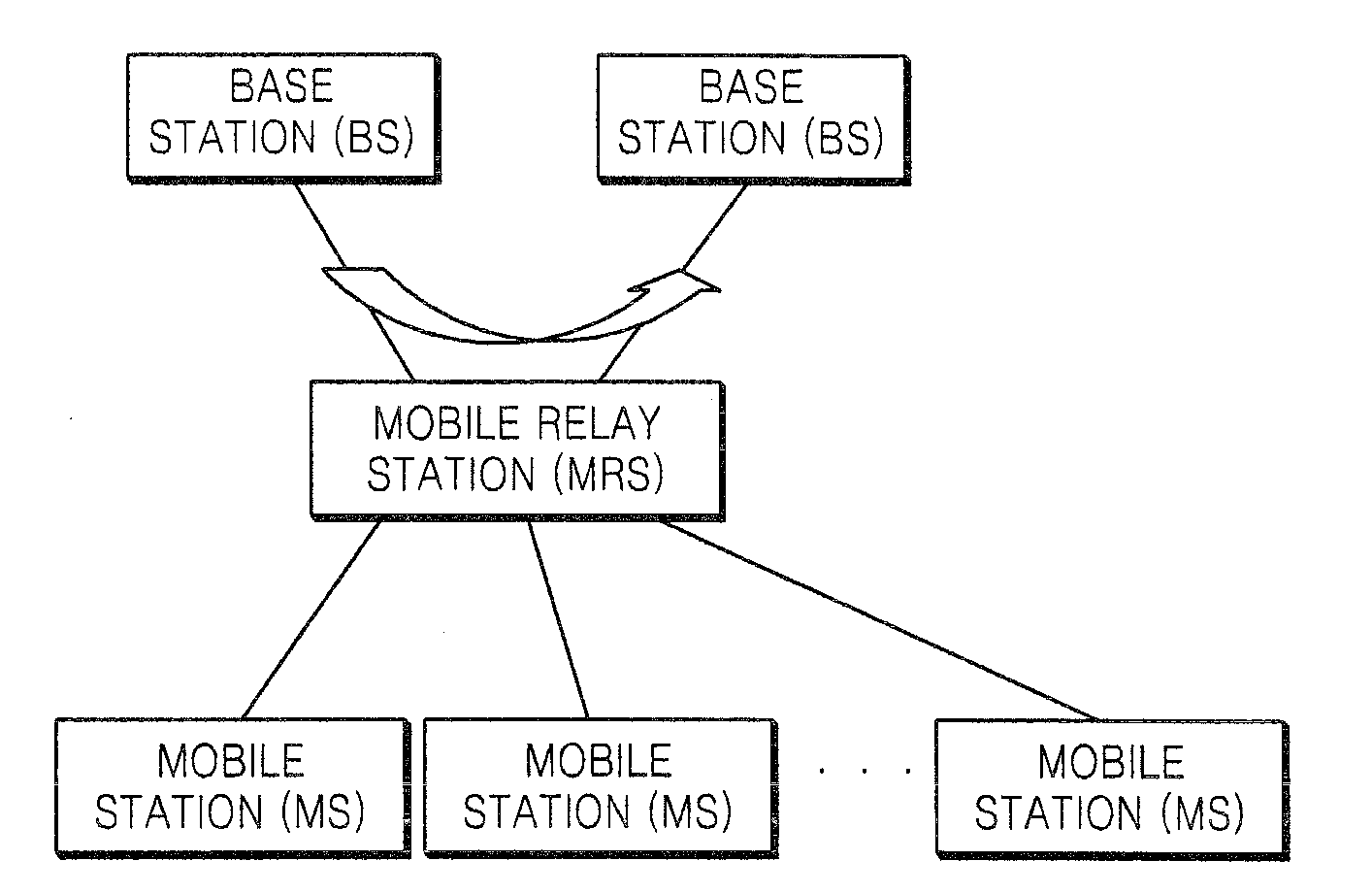
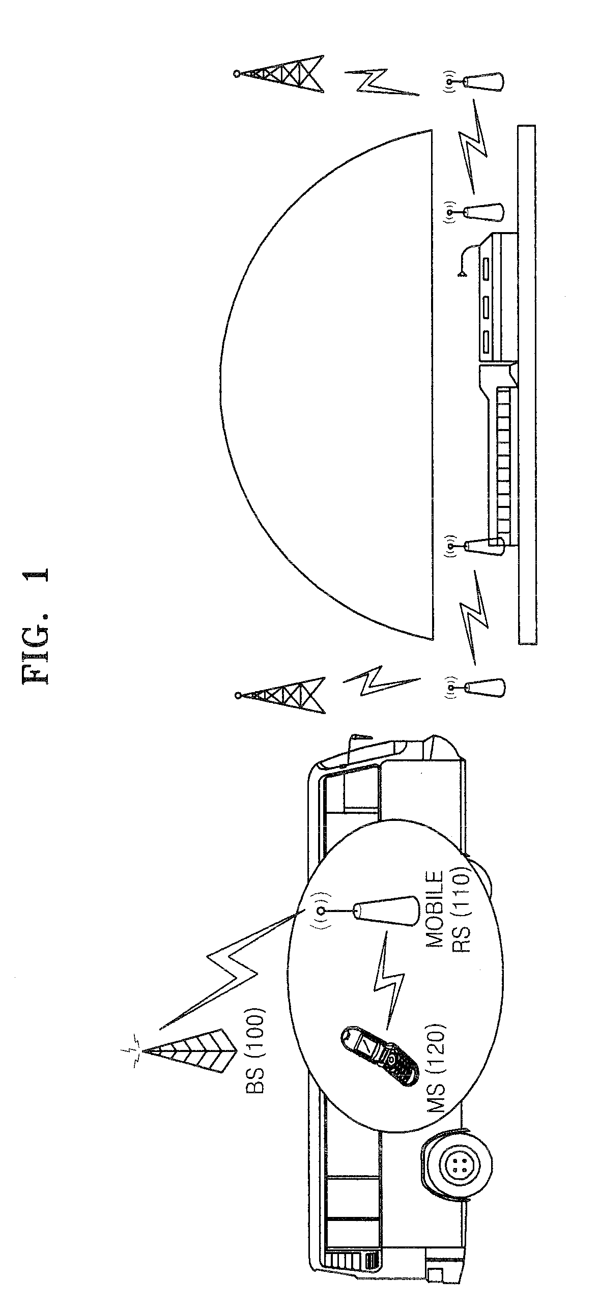
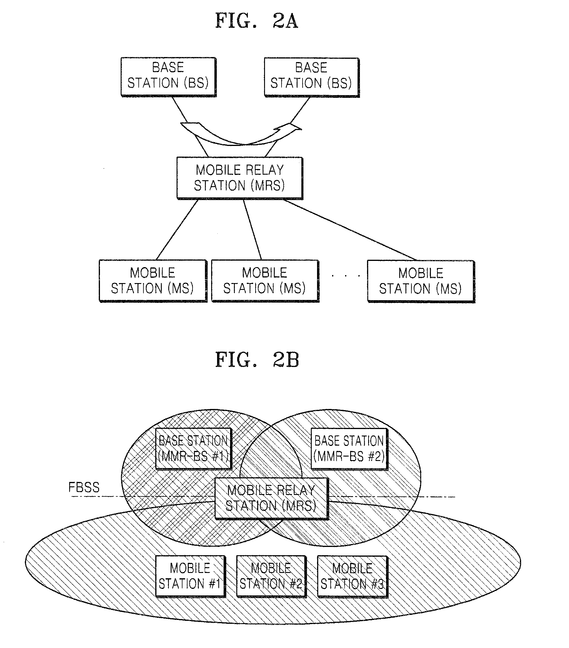
TECHNICAL FIELD[0001]The present invention relates to a handover method, and more particularly, to a handover method with a mobile relay station (MRS) in a wireless system.BACKGROUND ART[0002]FIG. 1 illustrates an example of a mobile relay station (MRS) suggested in IEEE 802.16j.[0003]An MRS 110, which is mounted on a mobile means such as a bus, train, or cruise, provides one or more multi-paths in order to provide a high speed wireless internet service to passengers. To provide a service to a mobile station (MS) 120 without breaking the connection in a broadband mobile internet system, a handover (HO) function between the MS 120 and a base station (BS) 100 has be considered. In order to support the handover function, hard HO (HHO) (FIG. 2a), fast base station switching (FBSS) (FIG. 2b), and macro diversity handover (MDHO) (FIG. 2c) techniques are suggested in IEEE 802.16e[0004]In general, a radio link between the BS 100 and the MRS 110 has a higher quality than a radio link between...

Claims


Application Information

Patent Timeline
Patent Type & Authority Applications(United States)
IPC IPC(8): H04W4/00
CPCH04W84/005H04W36/0005H04W36/08H04W36/38H04W36/0055H04W84/047
Inventor KIM, SUNG-KYUNGCHANG, SUNG-CHEOLYOON, CHUL-SIK
Owner ELECTRONICS & TELECOMM RES INST
Why Eureka
Try Eureka