Capacitve Sound Transducer Having a Perforated Attenuation Disk

Active Publication Date: 2010-03-11
SENNHEISER ELECTRONICS GMBH & CO KG
View PDF0 Cites 5 Cited by
  • Summary
  • Abstract
  • Description
  • Claims
  • Application Information

AI Technical Summary

Benefits of technology

[0007]The degree of nonlinearity can be reduced by decreasing the diaphragm deflection by means of suitable measures, for example by stronger air-gap attenuation. However, this gives rise to disadvantageous effects because the transducer sensitivity is reduced, as a result of which the noise characteristics of the microphone are also detrimentally affected.
[0008]One advantageous option for reducing the nonlinearity of the diaphragm deflection is provided by the “symmetrical push-pull converter”, as described in DE 43 07 825 A1, for example. It contains a second counterelectrode with properties identical to those of the first counterelectrode and which is disposed in front of the diaphragm in such a way that similar air gaps are formed on both sides of the diaphragm. In this case, the movement of the diaphragm causes opposite changes in resistance in the two air gaps, which mutually compensate each other. By this means, the movement of the diaphragm is linearized and the transducer distortions are minimized.
[0009]In push-pull converters, the change in capacitance between the two counterelectrodes and the diaphragm is generally evaluated by applying the HF principle, by connecting both counterelectrodes to the electric circuit of the microphone. The disadvantage this involves, namely that the additional counterelectrode disposed in front of the diaphragm is directly exposed to humidity, with the result that its electrical insulation can be weakened, does not have an effect when the HF principle is applied, because said principle results in very low electrical impedances.
[0010]In the case of condenser microphones and electret microphones operating according to the NF principle, electrical operation of the front counterelectrode would then lead to substantially greater moisture sensitivity due to the very high electrical impedances that then arise. Until now, this disadvantage has stood in the way of the push-pull principle being applied to these types of microphone.
[0011]Another disadvantage of the capacitive sound transducers used in known condenser microphones is that, in those regions lying opposite the perforated regions of the counterelectrode, the diaphragm produces partial natural oscillations at high frequencies, and these oscillations lead to undesired, frequency-dependent changes in the transmission characteristics of the condenser microphone. The frequencies at which partial oscillations occur are dependent on the mechanical tension of the diaphragm and on the size and shape of the counterelectrode perforations. In many cases, they are within the frequency transmission range, that is the specified operating frequency range, and lead to undesired frequency-dependent changes in the transmission characteristics of the condenser microphone.
[0012]This undesired oscillation behavior at high frequencies can be sufficiently suppressed in those regions of the diaphragm which lie opposite the non-perforated regions of the counterelectrodes, if the distance between the diaphragm and the counterelectrode is made so small that the viscosity of the air in the air gap formed by the diaphragm and the counterelectrode ensures sufficient attenuation of diaphragm movements. However, this attenuation is absent in those diaphragm regions which lie opposite the counterelectrode, with the consequence that the undesired natural oscillations of the diaphragm are not suppressed.

Problems solved by technology

All that remains is the internal attenuation of the diaphragm material and the influence of the surrounding air gap region, but this influence is hardly able to affect the perforated region via the low bending stiffness of the diaphragm.

Method used


Image

  • Capacitve Sound Transducer Having a Perforated Attenuation Disk
  • Capacitve Sound Transducer Having a Perforated Attenuation Disk
  • Capacitve Sound Transducer Having a Perforated Attenuation Disk

Examples


first embodiment

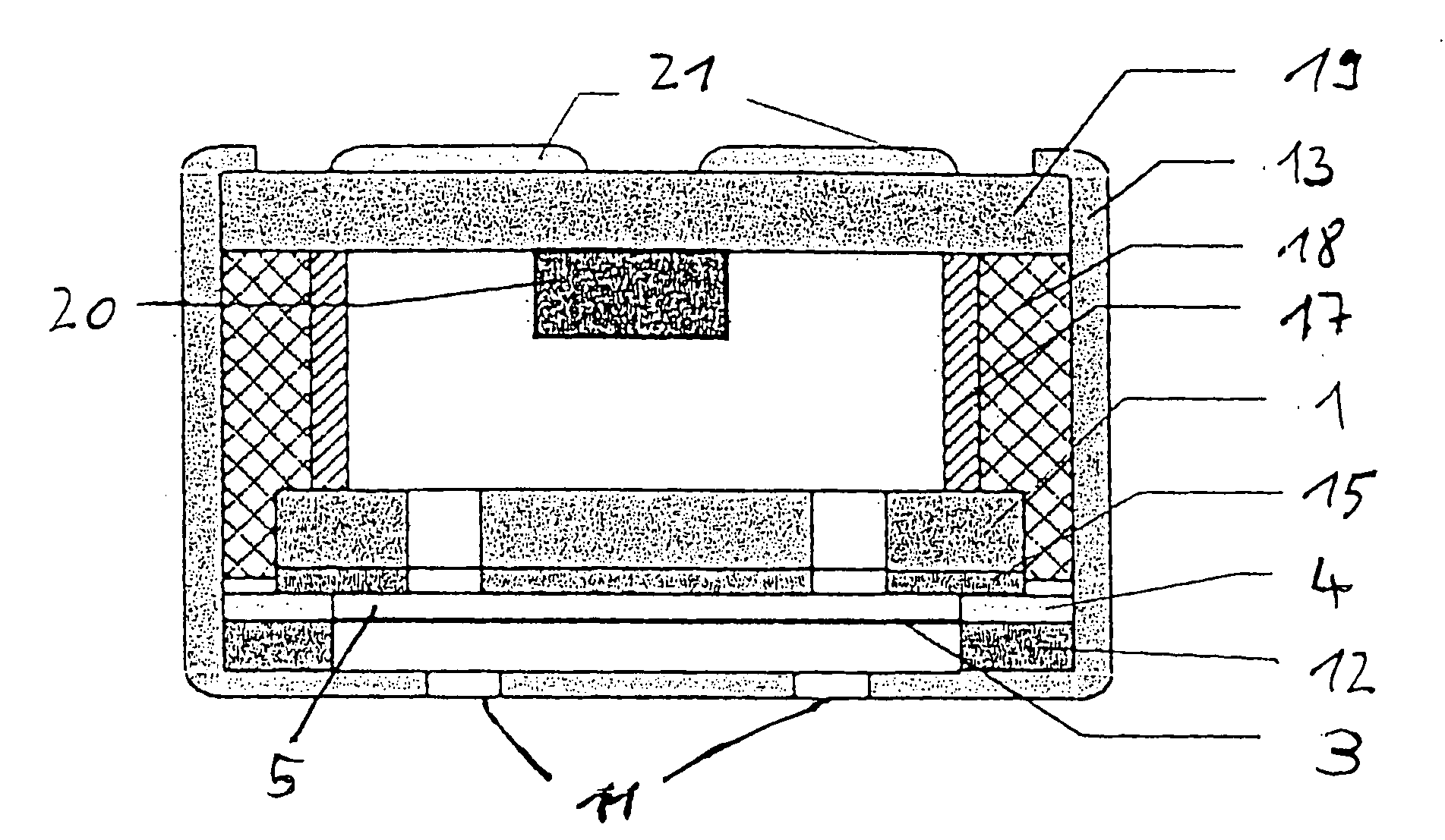
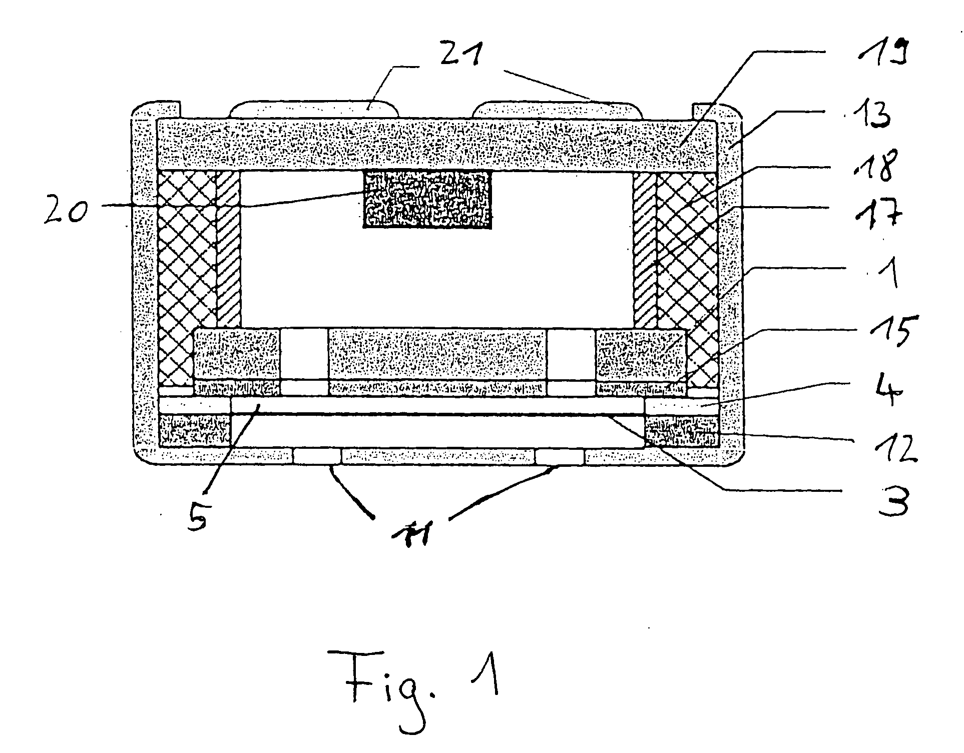
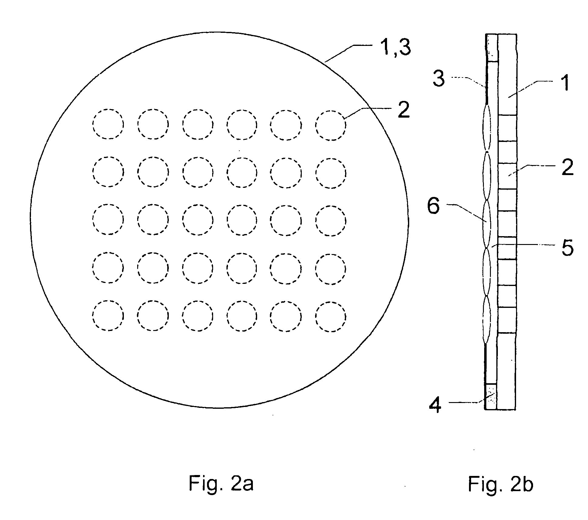
[0052]FIG. 3a and FIG. 3b show, analogously to FIG. 2a and FIG. 2b, the substantially modified elements of a capacitive sound transducer according to the invention. An additional attenuation disk 7 having perforations 8 (unbroken lines) is disposed in front of diaphragm 3. The two sets of perforations 2, 8 are offset in relation to each other in such a way that there is nowhere where they overlap. A spacer 9 similar to spacer 4 determines the distance between attenuation disk 7 and diaphragm 3, thus forming an second air gap 10. This results in diaphragm 3 being attenuated over its entire area by an air gap 5 and / or an air gap 10, that is to say, by at least one non-perforated region. In this way, the natural oscillations 6 of diaphragm 3 are efficaciously suppressed.

[0053]In the embodiment shown in FIG. 3a and FIG. 3b, first perforations 2 and second perforations 8 are offset from each other in such a way that perforated regions of the counterelectrode 1 lie opposite non-perforated...

second embodiment

[0054]FIG. 4 shows an example of a second embodiment according to the invention, in which perforation set 8 of attenuation disk-7 partially overlaps perforation set 2 of the counterelectrode 1 and in which perforation sets 2, 8 are arranged in rows. The first perforation set 2 and the second perforation set 8 are offset from each other in such a way that perforated regions of counterelectrode 1 each lie opposite a part of a first perforated region of attenuation disk-7 and at least one part of a second perforated region of attenuation disk-7. In this case also, efficacious attenuation of diaphragm 3 is achieved when the overlap is mainly in the edge regions of the perforations, with the result that sufficiently large attenuating areas of counterelectrode 1 and attenuation disk-7, respectively, particularly in the middle regions of the partial diaphragms, lie opposite the diaphragm, also in the perforated regions of perforation sets 2 and 8.

[0055]FIG. 5 shows an example of a third po...


PUM


Abstract

A capacitive sound transducer provided with a perforated attenuation disk. The invention further relates to a capacitive sound transducer and a condenser microphone having such a sound transducer. The sound transducer comprises a diaphragm and a counterelectrode which is disposed at a short distance from the diaphragm and provided with first perforations. In order to attenuate natural oscillations of the diaphragm at high frequencies, a capacitive sound transducer is proposed in which a sound-permeable attenuation disk provided with second perforations is disposed at a short distance from the diaphragm and opposite the counterelectrode. In this arrangement, the first perforations and the second perforations are also offset in relation to each other.

Description

CROSS-REFERENCE TO RELATED APPLICATIONS[0001]This is a national phase application of International Application No. PCT / EP2006 / 008865, filed Sep. 12, 2006 which claims priority of German Application No. 10 2005 043 664.1, filed Sep. 14, 2005, the complete disclosures of which are hereby incorporated by reference.BACKGROUND OF THE INVENTION[0002]a) Field of the Invention[0003]The invention relates to a capacitive sound transducer comprising a diaphragm and a counterelectrode which is disposed at a short distance from the diaphragm and provided with first perforations. The invention further relates to a condenser microphone provided with a capacitive sound transducer according to the invention.[0004]b) Description of the Related Art[0005]A capacitive sound transducer of a condenser microphone contains a planar diaphragm which is moved by sound, and a perforated counterelectrode parallel thereto at a short distance therefrom. The diaphragm and counterelectrode are designed to be electri...

Claims


Application Information

Patent Timeline
IPC IPC(8): H04R11/04
CPCH04R19/016H04R1/38
Inventor HIBBING, MANFRED
Owner SENNHEISER ELECTRONICS GMBH & CO KG
Why Eureka
Try Eureka