Fixing device, image forming apparatus including same, and fixing method

a technology of fixing device and image forming apparatus, which is applied in the direction of electrographic process apparatus, instruments, optics, etc., can solve the problems of difficult to spare enough space to provide temperature, difficult to solve the problem of expensive contactless temperature sensor such as a thermopile, and considerably limited positions to install the above-described temperature sensors. , to achieve the effect of preventing an excessive increase in temperature, reducing the degree of flexibility in types and installation positions

Active Publication Date: 2010-03-11
RICOH KK
View PDF6 Cites 109 Cited by
  • Summary
  • Abstract
  • Description
  • Claims
  • Application Information

AI Technical Summary

Benefits of technology

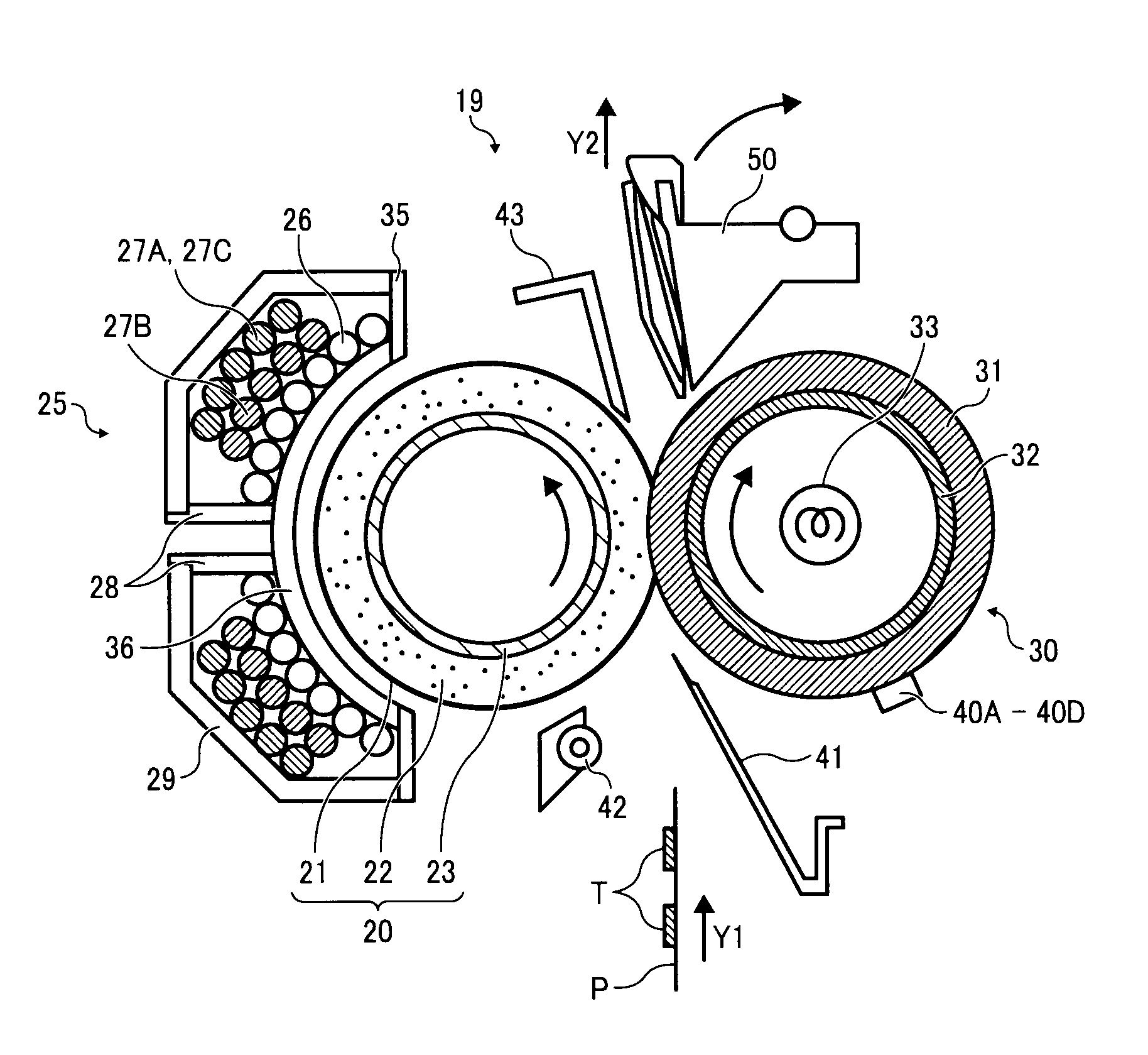
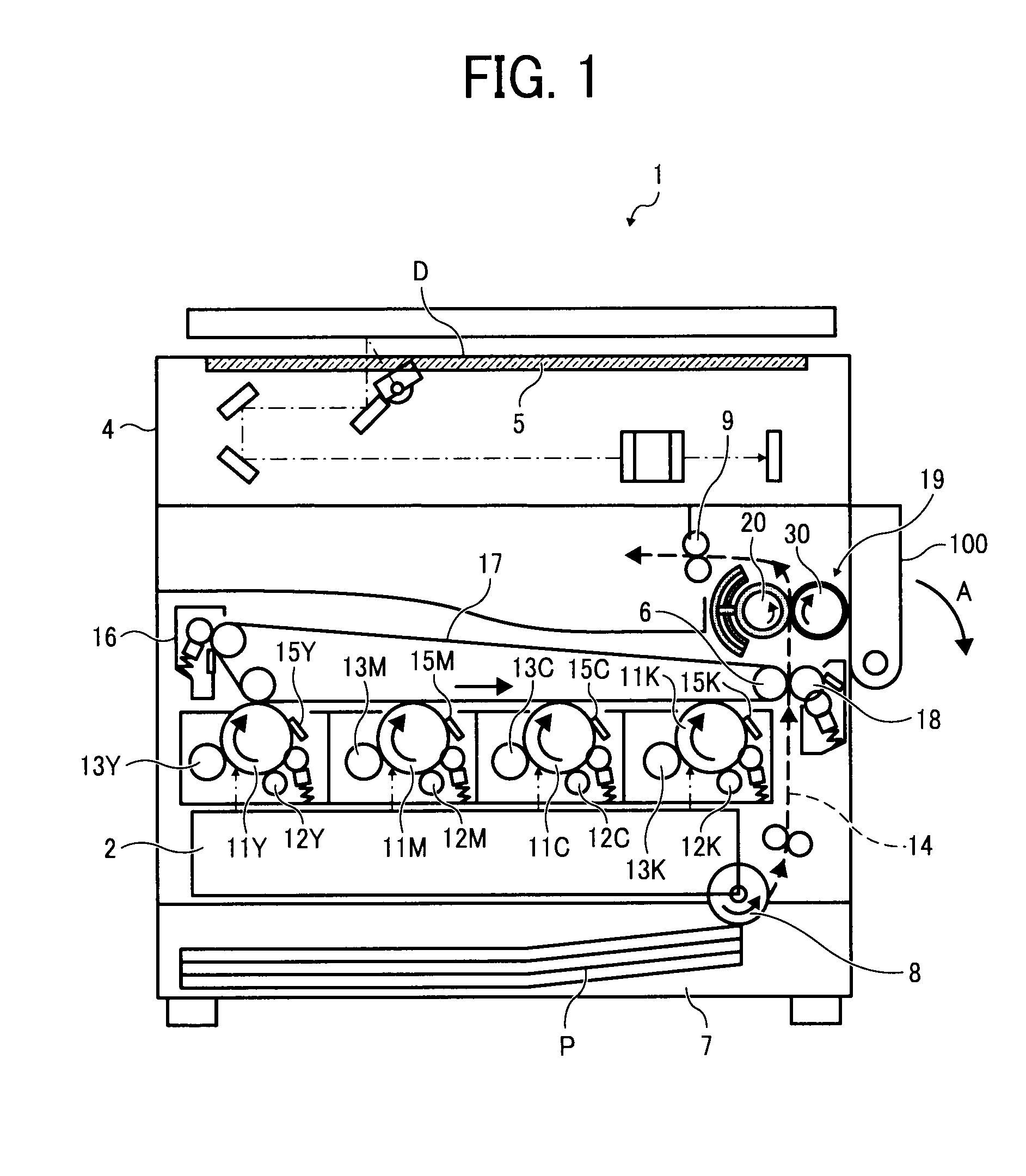
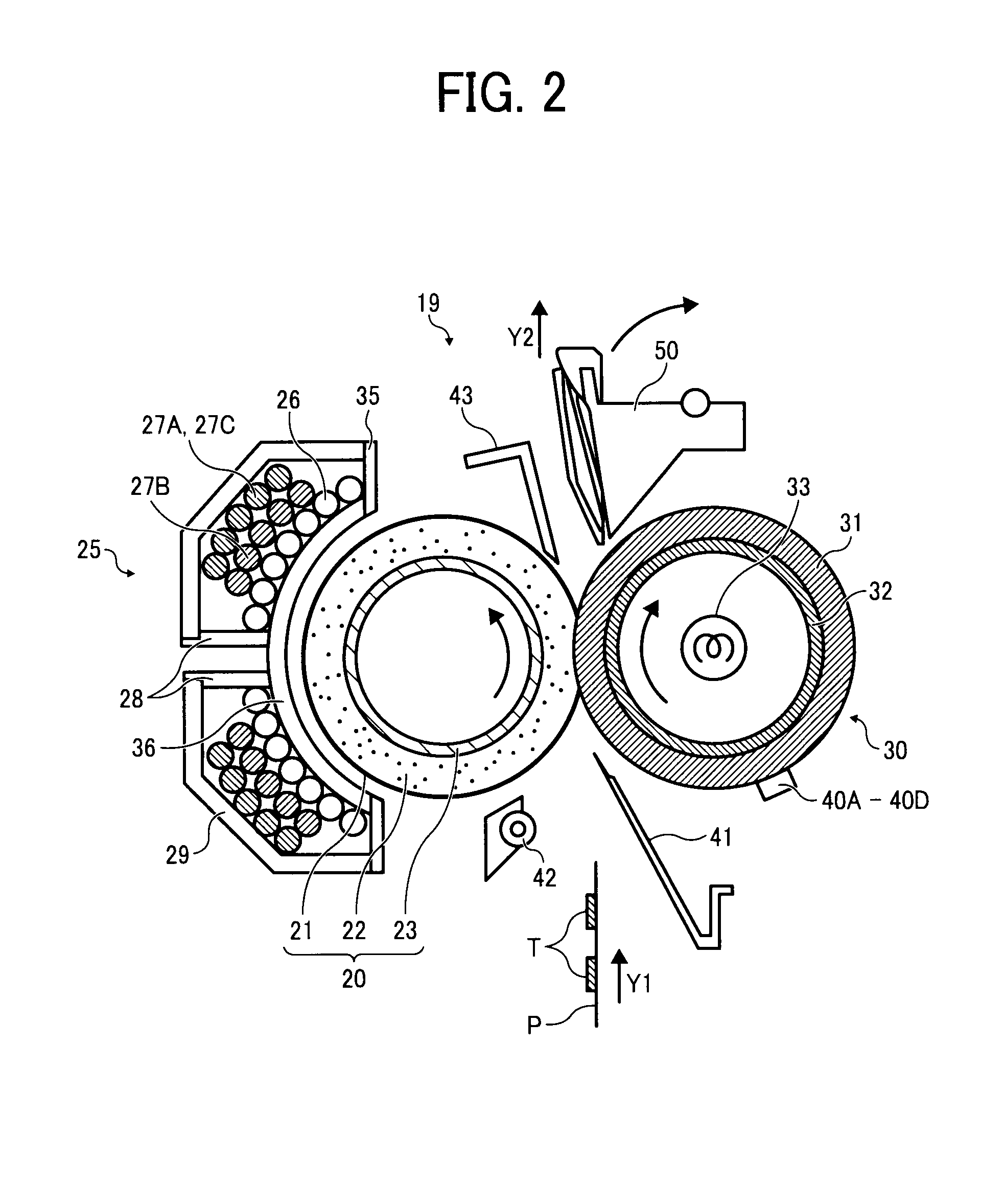
[0015]In view of the foregoing, illustrative embodiments of the present invention provide a fixing device that achieves a higher degree of flexibility in types and installation positions of a temperature detector provided therein to control an amount of power supplied to degaussing coils, and efficiently and reliably prevents an excessive increase in temperature at a non-conveyance portion of a fixing member using the degaussing coils. Illustrative embodiments of the present invention further provide an image forming apparatus including the fixing device, and a fixing method employed in the fixing device.

Problems solved by technology

However, both the number of types of the above-described temperature sensor for controlling an amount of power supplied to the degaussing coil and positions to install the above-described temperature sensors are considerably limited.
Consequently, an expensive contactless temperature sensor such as a thermopile is required to solve the above-described problem.
Further, because a larger number of components including an exciting coil, the degaussing coil, a separation plate, and so forth are densely packed around the fixing member, it is difficult to spare enough space to provide the temperature sensor to detect the temperature at the edge of the fixing member in the width direction thereof.
However, because a difference in a temperature between the fixing member and the pressing member is not always kept constant, it is difficult to control the amount of power supplied to the degaussing coils by indirectly detecting an increase in temperature at the non-conveyance portion of the fixing member based on the result detected by the single temperature sensor provided at the edge of the pressing member in the width direction thereof.
In other words, an increase in temperature at the non-conveyance portion of the fixing member may fail to be detected accurately, allowing an excessive increase in temperature in the non-conveyance portion of the fixing member and a decrease in temperature at an edge of a conveyance portion of the fixing member covered by the sheet.

Method used


Image

  • Fixing device, image forming apparatus including same, and fixing method
  • Fixing device, image forming apparatus including same, and fixing method
  • Fixing device, image forming apparatus including same, and fixing method

Examples


Embodiment Construction

[0027]In describing illustrative embodiments illustrated in the drawings, specific terminology is employed for the sake of clarity. However, the disclosure of this patent specification is not intended to be limited to the specific terminology so selected, and it is to be understood that each specific element includes all technical equivalents that operate in a similar manner and achieve a similar result.

[0028]Illustrative embodiments of the present invention are now described below with reference to the accompanying drawings.

[0029]In a later-described comparative example, illustrative embodiment, and exemplary variation, for the sake of simplicity the same reference numerals will be given to identical constituent elements such as parts and materials having the same functions, and redundant descriptions thereof omitted unless otherwise required.

[0030]A description is now given of a configuration and operations of an image forming apparatus according to illustrative embodiments with r...


PUM


Abstract

A fixing device including a fixing member to melt a toner image to fix the toner image to a recording medium, a pressing member pressed against the fixing member to form a nip to where the recording medium is conveyed, multiple temperature detectors to detect a temperature at multiple positions on a surface of the pressing member in a width direction thereof, a heating member including a heating layer to heat the fixing member; an exciting coil to generate magnetic fluxes to inductively heat the heating layer, and one or more pairs of degaussing coils to generate magnetic fluxes to degauss the magnetic fluxes generated by the exciting coil. An amount of power supplied to the one or more pairs of degaussing coils is controlled based on a result detected by each of the multiple temperature detectors.

Description

CROSS-REFERENCE TO RELATED APPLICATIONS[0001]The present patent application is based on and claims priority pursuant to 35 U.S.C. §119 from Japanese Patent Application No. 2008-230527, filed on Sep. 9, 2008 in the Japan Patent Office, the entire contents of which are incorporated herein by reference.BACKGROUND OF THE INVENTION[0002]1. Field of the Invention[0003]Exemplary aspects of the present invention generally relate to a fixing device, an image forming apparatus including the fixing device, and a fixing method employed in the fixing device, and particularly to a fixing device employing an electromagnetic induction heating method using degaussing coils, and an image forming apparatus including the fixing device.[0004]2. Description of the Background[0005]Related-art image forming apparatuses, such as copiers, facsimile machines, printers, or multifunction devices having two or more of copying, printing, scanning, and facsimile functions, typically form a toner image on a recordi...

Claims


Application Information

Patent Timeline
Patent Type & Authority Applications(United States)
IPC IPC(8): G03G15/20G03G13/20
CPCG03G15/2042
Inventor HASE, TAKAMASA
Owner RICOH KK
Why Eureka
Try Eureka