Multicomponent taggant fibers and method

Inactive Publication Date: 2010-03-11
INTELLECTUAL PROD PROTECTION +1
View PDF2 Cites 20 Cited by
  • Summary
  • Abstract
  • Description
  • Claims
  • Application Information

AI Technical Summary

Benefits of technology

[0015]The aforesaid and other objectives are realized by providing a polymeric yarn or fiber composed of two zones which are aligned in parallel along the fiber length. Each zone includes a taggant having different optical activity such that the two taggants provide optically distinguishable signals in response to two separate stimuli. One taggant may be an inorganic compound while the other taggant may consist of an organic compound. The two optically active materials may be segregated in separate polymer components of a multicomponent filament to prevent or mitigate adverse chemical reactions between the two taggants. The invention may also comprise an individual fiber in which the optically active materials are co-dispersed in the fiber or segregated in separate polymer components or zones of a multicomponent fiber.
[0016]The present invention provides advantages over the prior art in that it has improved stealth and security for inclusion in articl

Problems solved by technology

The inclusion of two chemically incompatible active materials segregated in separate polymer components or separate

Method used


Image

  • Multicomponent taggant fibers and method
  • Multicomponent taggant fibers and method
  • Multicomponent taggant fibers and method

Examples


example 1

[0047]Continuous multi-filament melt spun fiber is produced using a bicomponent extrusion system.

[0048]The sheath component of the bicomponent fiber consists of polyethylene terephthalate with an inherent viscosity of 0.64, blended with finely-divided particles of a suitable fluorophore at a loading of between 0.1 and 3.0 percent by weight.

[0049]The core component consists of polyethylene terephthalate with an inherent viscosity of 0.64, blended with finely-divided particles of yttrium oxide at a loading of between 0.1 and 3.0 percent by weight.

[0050]The weight ratio of sheath to core is 50 / 50. The two components are subjected to sheath-and-core type conventional bicomponent melt spinning. The filaments are subsequently drawn, thereby yielding a three (3) denier multifilament fiber.

example 2

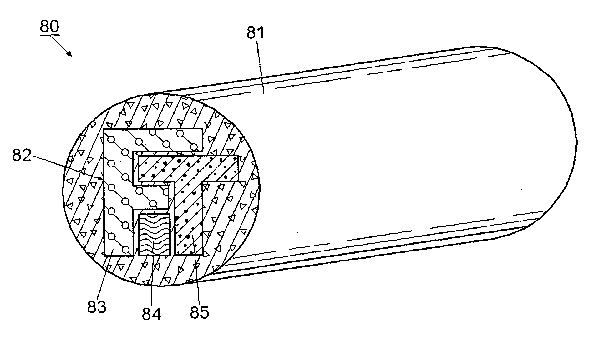
[0051]A continuous multi-filament melt spun fiber is produced using a bicomponent extrusion system forming a core and sheath as shown in FIG. 8.

[0052]The first zone comprises a sheath of the bicomponent fiber consisting of polyethylene terephthalate with an inherent viscosity of 0.64, blended with finely-divided particles of a suitable fluorophore at a loading of between 0.1 and 3.0 percent by weight.

[0053]The second zone comprises three core members consisting of polyethylene terephthalate with an inherent viscosity of 0.64, blended with finely-divided particles of yttrium oxide at a loading of between 0.1 and 3.0 percent by weight. The three core members represent the letters “F”, “I” and “T” which form a company logo and are numbered 83, 84, 85 respectively. Each separate core member (83, 84 or 85) may contain the same or different taggants and may be formed of the same or different polymers.

[0054]The weight ratio of sheath to the three core members is approximately 50 / 50%. Two m...


PUM

PropertyMeasurementUnit
Lengthaaaaaaaaaa
Fluorescenceaaaaaaaaaa

Abstract

Taggant fibers and methods of use provide for enhanced protection and security when the fibers are used in documents such as land titles, currency, passports and other documents of value. The taggant fibers consist of a minimum of two separate zones with each zone containing a different taggant to emit different wave lengths when excited. The taggants may consist of organic or inorganic compounds as are conventionally known and can be manufactured using for example polymeric materials which can be extruded during the fiber manufacturing process. A first zone may comprise a fiber sheath which includes a taggant and a second or inner zone or core which may be formed into a company logo having letters with different or the same taggants. Authentication of the fibers or documents containing such fibers can be readily viewed using conventional techniques.

Description

[0001]This is a continuation-in-part of and claims benefits under pending prior patent application Ser. No. 12 / 205,993 filed 8 Sep. 2008, now U.S. Pat. No. ______.FIELD OF THE INVENTION[0002]The invention herein pertains to fibers which contain a taggant and particularly pertains to multicomponent taggant fibers and methods of producing the same.DESCRIPTION OF THE PRIOR ART AND OBJECTIVES OF THE INVENTION[0003]The need for secure documents, cards, licenses and the like has increased dramatically in recent years due to the expansion of international commerce through the global information network. Banks and other financial institutes are constantly seeking ways to protect and authenticate documents which are often used in fraudulent schemes to acquire property, identities, credit and money. It is well known to incorporate optically active taggants into various documents which luminesce, fluoresce or emit various energy wave lengths that can be easily identified. These emissions may b...

Claims


Application Information

Patent Timeline
IPC IPC(8): B32B27/02D01D5/00C08K3/20C08L67/00
CPCC08K2003/221C08L67/02D01D5/30D01F1/10D21H15/00Y10T428/2929Y10T428/2967Y10T428/294Y10T428/2931Y10T428/2969D21H21/40
Inventor MERCHANT, TIMOTHY P.DUGAN, JEFFREY S.
Owner INTELLECTUAL PROD PROTECTION
Why Eureka
Try Eureka