Combination device for snow throwing, mowing, scarifying, soil breaking or the like

a combination device and technology of mowing and scarifying, applied in the direction of snow cleaning, road cleaning, mowers, etc., can solve the problems of not being able to optimize all its functionalities, not being able to provide a further distance for displacing snow, and affecting the operation of the device, so as to simplify the change of different work implements and optimize the effect of functional optimization

Active Publication Date: 2010-03-18
PAPST MOTOREN GMBH & CO KG
View PDF12 Cites 8 Cited by
  • Summary
  • Abstract
  • Description
  • Claims
  • Application Information

AI Technical Summary

Benefits of technology

[0012]The deficiency just described is overcome in accordance with the present invention wherein the changing of different work implements is simplified and functionally optimized.

Problems solved by technology

Such combination device is penalized by the fact that not all its functionalities can be optimally designed for all the work tasks.
In particular, in the case of snow throwing, a discharge chute is not provided for displacing snow at a further distance away during or at the end of the snow cutting process.
Another disadvantage lies in the drive axis which, depending on the functionality, is supported from one side only, thereby leading to instability.
Furthermore, the device may for example be hampered by its inability to allow for height adjustment or the separation between the work implement and ground.
The device is extremely troublesome to set up and requires individual housing for each work implement to be attached onto the main device housing.
However, the changing of work implements is complicated by the housing, whose side wall has to be physically dismounted first, by undoing a number of bolts, before finally being able to change over the work implements.
Additional housing covers or housing attachments are included for the different functionalities, which further complicate the tool setup not to mention the provision for additional storage of individual parts.

Method used


Image

  • Combination device for snow throwing, mowing, scarifying, soil breaking or the like
  • Combination device for snow throwing, mowing, scarifying, soil breaking or the like
  • Combination device for snow throwing, mowing, scarifying, soil breaking or the like

Examples


Embodiment Construction

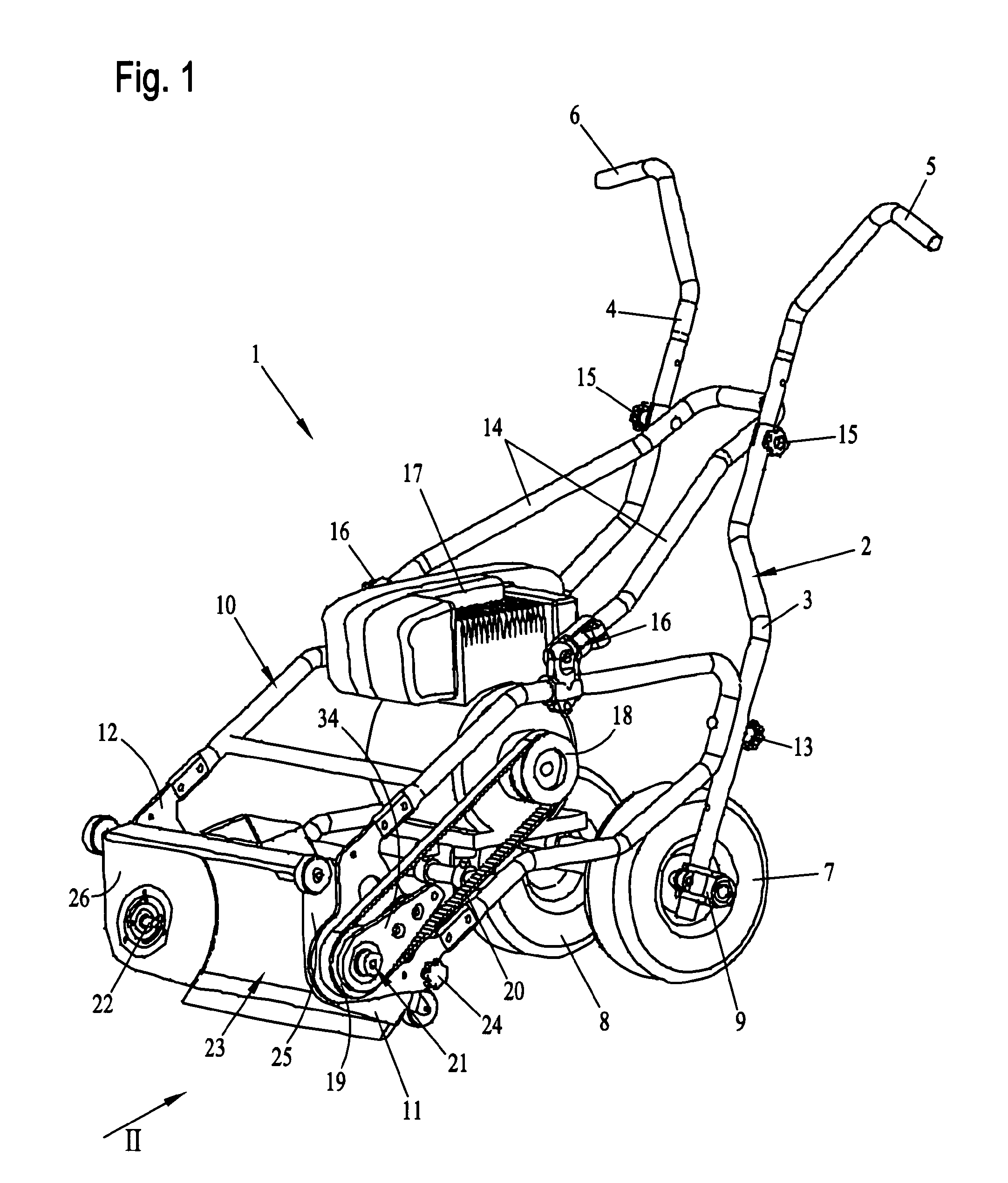
[0044]Referring to the drawings in particular, FIG. 1 shows the principal configuration of a combination device 1 in its perspective view.

[0045]To the rear of the combination device, 1 a wheel frame 2 is shown and which comprises two bent guide rods 3 and 4, whose upper ends transform into the respective hand grips 5 and 6. At the lower end of the guide rods 3 and 4, two wheels 7 and 8 are mounted by means of fixture 9 which enables height adjustment along the guide rods 3 and 4.

[0046]Furthermore, the combination device exhibits a base frame 10, whose front end is mounted with two vertical side plates 11 and 12. The side plates 11 and 12 are fixed onto but detachable from the base frame 10. The base frame 10 is bolted together with the lower parts of the guide rods 3 and 4 by means of the palm grip 13.

[0047]In order to support and strengthen the combination device 1, a stiffening bracket 14 is seen in the present embodiment with one end being attached to the guide rods 3 and 4 by me...


PUM


Abstract

A combination device (1) is provided for carrying out various work tasks, such as cutting snow, mowing, scarifying, soil breaking or the like. The device includes a plurality of interchangeable work implements (60) tailored to the respective work task. A basic frame is provided in which the respective work implement (60) is accommodated and can be driven to rotate, and wherein the respectively installed work implement (60) is partially enclosed by a housing (23) extending parallel to the axis of rotation of the work implement. In order to tailor the combination device optimally to the respective work task, provision is made for the housing (23) to be able to rotate about an axis parallel to the axis of rotation of the respective work implement (60) and to be fastened in various operating positions corresponding to the respective work task.

Description

CROSS REFERENCE TO RELATED APPLICATIONS[0001]This application is a United States National Phase application of International Application PCT / EP2007 / 009616 and claims the benefit of priority under 35 U.S.C. §119 of German Patent Application DE 20 2006 016 981.4 filed Nov. 7, 2006, the entire contents of which are incorporated herein by reference.FIELD OF THE INVENTION[0002]The present invention relates to a combination device for performing different tasks such as snow throwing, mowing, scarifying, soil breaking, sweeping or the like by means of interchanging the work implements such that each implement is adapted for each respective task, whereby a machine frame is intended for taking on the respective work implement and letting it be driven in rotation, and that the respectively installed work implement is enclosed by a partially open cylindrical housing the rotational axis of which lies in parallel to that of the work implement.BACKGROUND OF THE INVENTION[0003]Combination devices ...

Claims


Application Information

Patent Timeline
Patent Type & Authority Applications(United States)
IPC IPC(8): E01H5/09E01H5/04A01D42/00
CPCA01B45/00E01H5/04A01D42/08
Inventor LAU, ADREW MANSON
Owner PAPST MOTOREN GMBH & CO KG
Why Eureka
Try Eureka