Method of forecasting the lifetime of structural parts

a technology of structural parts and lifetime prediction, applied in the direction of material strength using repeated/pulse forces, instruments, material analysis, etc., can solve the problems of component failure, component wakening and eventually failing, and strain gauge on its own not useful in predicting the remaining life of the component,

Active Publication Date: 2010-03-18
PARADIGM SHIFT TECH
View PDF19 Cites 6 Cited by
  • Summary
  • Abstract
  • Description
  • Claims
  • Application Information

AI Technical Summary

Problems solved by technology

Repeated stress / strain cycles have a cumulative effect causing the component to waken and eventually fail.
Accordingly, a strain gauge on its own is not useful in predicting the remaining life of the component.
While a strain gauge could be augmented with a recording apparatus (for example a microprocessor) for recording loading history, this is generally impractical and in many applications impossible.
For example if one wishes to monitor the loading history of a gear or a spring encased in a housing, there is no way in which to connect electrical leads to the strain gauge.

Method used


Image

  • Method of forecasting the lifetime of structural parts
  • Method of forecasting the lifetime of structural parts
  • Method of forecasting the lifetime of structural parts

Examples


Embodiment Construction

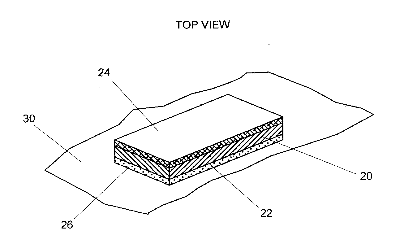
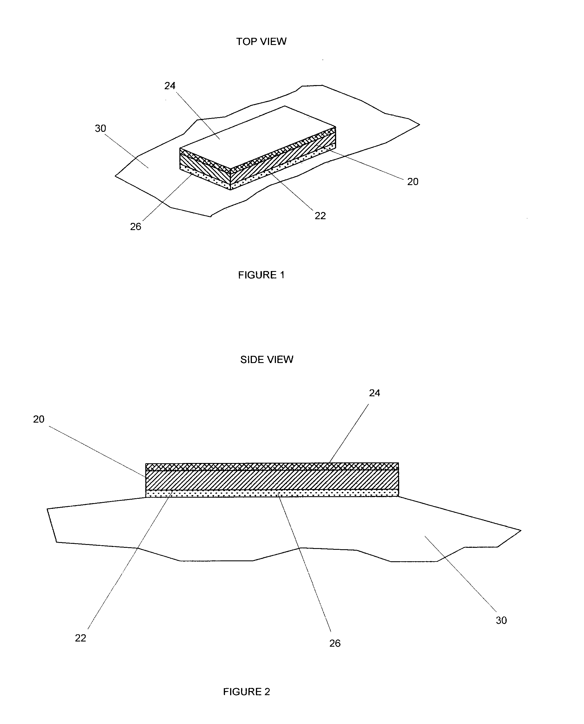
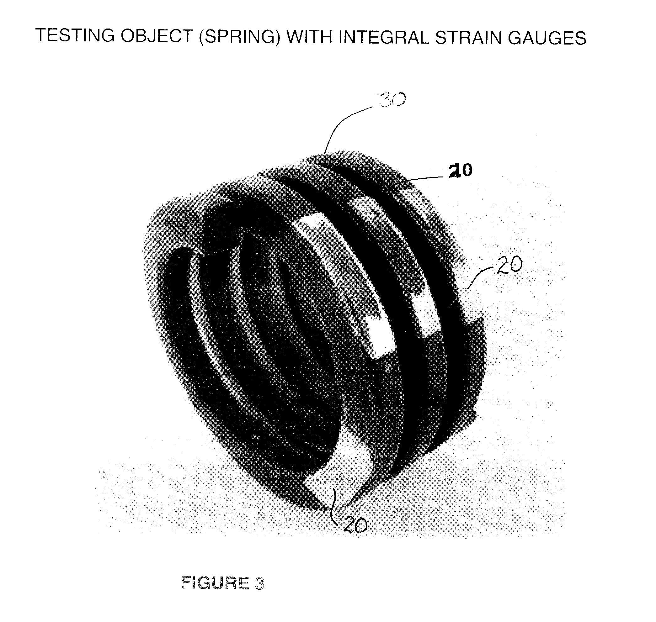
[0049]According to the present invention, as illustrated in FIGS. 1-3, a gauge material 20 is selected which undergoes a progressive, cumulative and quantifiable change in at least one of its physical properties in response to repeated strain cycles applied thereto. The gauge should be of a form and dimensions to be attachable to a component or a part 30 being monitored. For example the strain gauge 20 illustrated is in the form of a strip having substrate 22 with a reflective coating 24 on one face and affixing means such as an adhesive 26 on its opposite face.

[0050]The reflective coating 24 diminishes in reflectivity as the strain gauge 20 is repeatedly stressed. The diminishment of reflectivity may be caused by microstructural changes of either or both the substrate and the reflective coating.

[0051]The reflective coating 24 may simply be an outer surface of the substrate 22. The strain gauge 20 may therefore be a metal foil strip of 10 to 15 μm thickness glued to or plated on the...


PUM

PropertyMeasurementUnit
thicknessaaaaaaaaaa
cyclic stress fatigueaaaaaaaaaa
physical propertiesaaaaaaaaaa

Abstract

A method is provided for determining the extent of cyclic stress fatigue suffered by a component comprising the steps of: (i) obtaining a gauge material which undergoes a continued progressive / cumulative and quantifiable change in at least one of its physical properties in response to repeated strain cycles applied to the gauge material, the quantifiable change being indicative of both degree of strain and number of cycles incurred during the repeated strain cycles; (ii) determining a correlation between an extent of the quantifiable change in the gauge material and an effect on said component of a corresponding number and degree of strain cycles; (iii) affixing the gauge material to said component to subject the gauge material to any strain encountered by an adjacent portion of the component; (iv) at least periodically determining the extent of said quantifiable change to the gauge material to determine the extent of cyclic stress fatigue undergone by the component.

Description

FIELD OF THE INVENTION [0001]This invention relates generally to mechanical testing. More particularly, this invention relates to methods of determining the lifetime of a machine part or component which is subject to cyclic stress.BACKGROUND OF THE INVENTION [0002]When a component is subject to sufficient stress forces it reacts by undergoing dimensional change, referred to as “strain”. Stress and strain are related by the “Modulus of Elasticity” of the material of said component and accordingly, reference to one is indirectly a reference to the other.[0003]Stress and strain have an indelible effect on the material at the microscopic and possibly even molecular level. For small amounts of stress / strain within the elastic range of the material, the effect of each stress / strain cycle is virtually negligible. Repeated stress / strain cycles have a cumulative effect causing the component to waken and eventually fail. The number of cycles to failure generally is a function of the amount of...

Claims


Application Information

Patent Timeline
Patent Type & Authority Applications(United States)
IPC IPC(8): G01N3/32
CPCG01N3/32G01B11/16
Inventor OUDOVIKINE, ALEXANDRE
Owner PARADIGM SHIFT TECH
Why Eureka
Try Eureka