Grate-type ball mill and grid plate for ball mill

A ball mill and grid plate technology, which is applied to grain processing and other directions, can solve the problems of ball mill discharge efficiency and service performance, grid hole wear, forced shutdown of production and maintenance, etc., so as to improve the discharge efficiency and performance, improve Grinding ability, the effect of not easy slurry backflow

Inactive Publication Date: 2016-12-07
陈江
View PDF11 Cites 5 Cited by
  • Summary
  • Abstract
  • Description
  • Claims
  • Application Information

AI Technical Summary

Problems solved by technology

[0004] Due to the defects of the grid plate structure and the design of the center liner, the traditional grid-type ball mill often has problems such as the center liner falling off, the service life is short, and the use and production are forced to stop for maintenance, which seriously affects the normal production of the concentrator. Arranged concentrically, the slurry flows along the grid, the grid holes are severely worn, and the slurry is easy to flow back; the grid holes are arranged radially, and the ore particles are centrifugally affected when they pass through the grid plate, and move outward along the hole, which is easy to cause blockage. Although these two types of grid holes play a role It plays the role of grid plate holes, but its shortcomings have a serious impact on the discharge efficiency and performance of the ball mill

Method used


Image

  • Grate-type ball mill and grid plate for ball mill
  • Grate-type ball mill and grid plate for ball mill
  • Grate-type ball mill and grid plate for ball mill

Examples


Embodiment Construction

[0018] The present invention is described in further detail now in conjunction with accompanying drawing. These drawings are all simplified schematic diagrams, which only illustrate the basic structure of the present invention in a schematic manner, so they only show the configurations related to the present invention.

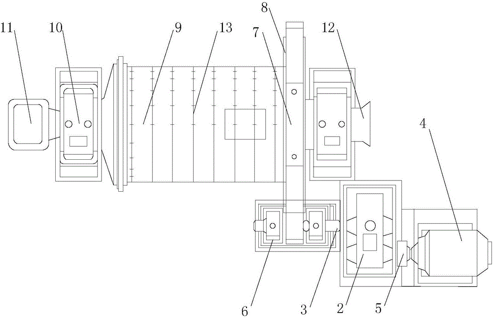
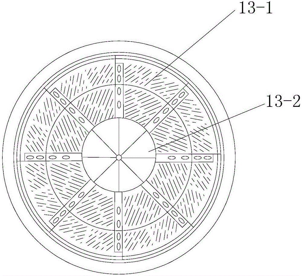
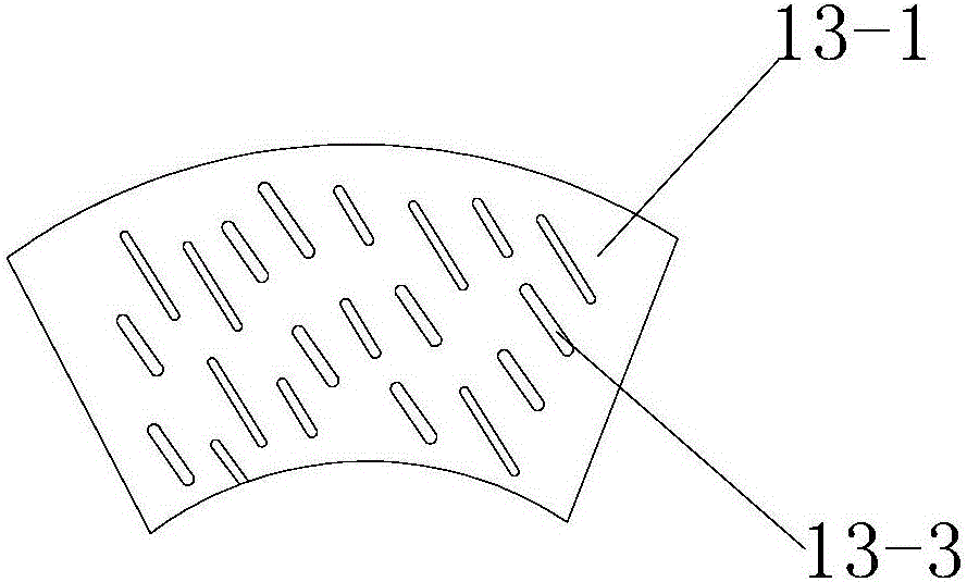
[0019] Such as Figure 1~4 A grid-type ball mill and a grid plate for a ball mill shown in the figure have a cylinder part 9 and a reducer 2. One end of the reducer 2 is connected to the motor 4 through the coupling I3, and the other end is connected to the small transmission gear through the coupling II5. 6 connection, the small transmission gear 6 is connected with the large rotary gear 8 arranged on the hollow shaft 7 through a sprocket, the hollow shaft 7 is provided with a cylinder part 9, and one end of the cylinder part 9 is connected with the main bearing part 10, and the main shaft The bearing part 10 is connected to the feeding part 11, and the barr...


PUM


Abstract

The invention relates to a grate-type ball mill and a grid plate for the ball mill. The grate-type ball mill comprises a cylinder and a speed reducer, one end of the speed reducer is connected with a motor through a coupler I, the other end of the speed reducer is connected with a small transmission gear through a coupler II, the small transmission gear is connected with a large turning gear on a hollow shaft through a sprocket, the cylinder is arranged on the hollow shaft, one end of the cylinder is connected with a main bearing, the main bearing is connected with a feeding portion, and a discharging portion opposite to the feeding portion is arranged on the cylinder. Ore grinding capacity is improved, firmness and non-falling are ensured in the running process of the ball mill, bolts are prevented from loosening or breaking due to cyclic stress, the ball mill is long in service life, low in grid hole abrasion and not easy to block, working efficiency is improved, ore pulp backflow is not easily generated, and the ore discharge efficiency and the service performance of the ball mill are improved.

Description

technical field [0001] The invention relates to a grid type ball mill and a grid plate for the ball mill. Background technique [0002] The ball mill uses steel balls as the crushing medium to grind ore. It is the most common and versatile grinding equipment in industrial sectors such as beneficiation and metallurgy. obtain higher processing capacity; [0003] The main functions of the grid plate are: 1) to realize the forced ore discharge (low-level ore discharge) of the grinding machine, the turnover of the ore material is fast, and the overgrinding is light, which is conducive to improving the grinding capacity; 2) the width of the grid hole of the grid plate The direction of the ore gradually expands (trapezoid), which can prevent the diversion of the slurry and the blockage of large ore particles; 3) It plays a screening role to prevent the discharge of large ore materials and ground media. [0004] Due to the defects of the grid plate structure and the design of the ...

Claims


Application Information

Patent Timeline
Patent Type & Authority Applications(China)
IPC IPC(8): B02C17/10B02C17/22B02C17/24
CPCB02C17/10B02C17/22B02C17/24
Inventor 陈江
Owner 陈江
Why Eureka
Try Eureka