Oil Pan Baffle

Active Publication Date: 2010-03-18
MANN HUMMEL GMBH
0 Cites 19 Cited by

AI-Extracted Technical Summary

Problems solved by technology

This is disadvantageous because an additional mounting step for attaching the oil pan baffle is re...

Benefits of technology

[0004]It is therefore an object of the present invention...

Abstract

An oil pan baffle is secured by a securing device on the oil pan. The securing device has an oil pan gasket with a gasket body matched to a sealing contour of an oil pan relative to a crankcase and securing elements that are connected to the gasket body and project inwardly away from an inner perimeter of the gasket body. The securing elements act on contact surfaces of the oil pan baffle, with which contact surfaces the oil pan baffle is positioned in receptacles of the oil pan, and exert pressure effecting secure fixation of the oil pan baffle on the oil pan when the oil pan gasket is compressed by mounting the oil pan on the crankcase.

Application Domain

CasingsEngine seals +3

Technology Topic

CrankcaseGasket +1

Image

  • Oil Pan Baffle
  • Oil Pan Baffle
  • Oil Pan Baffle

Examples

  • Experimental program(1)

Example

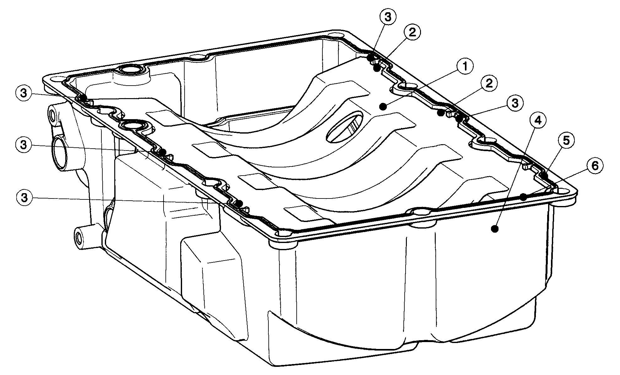
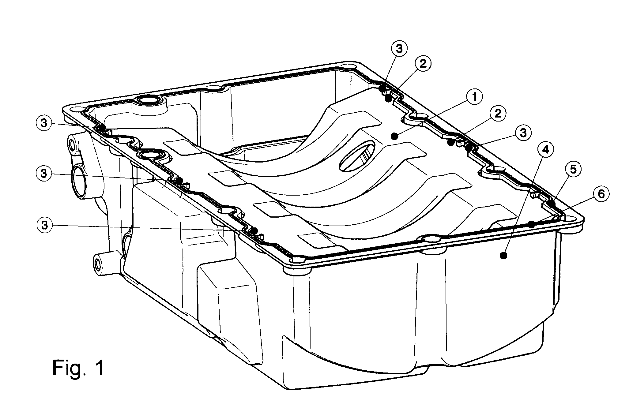
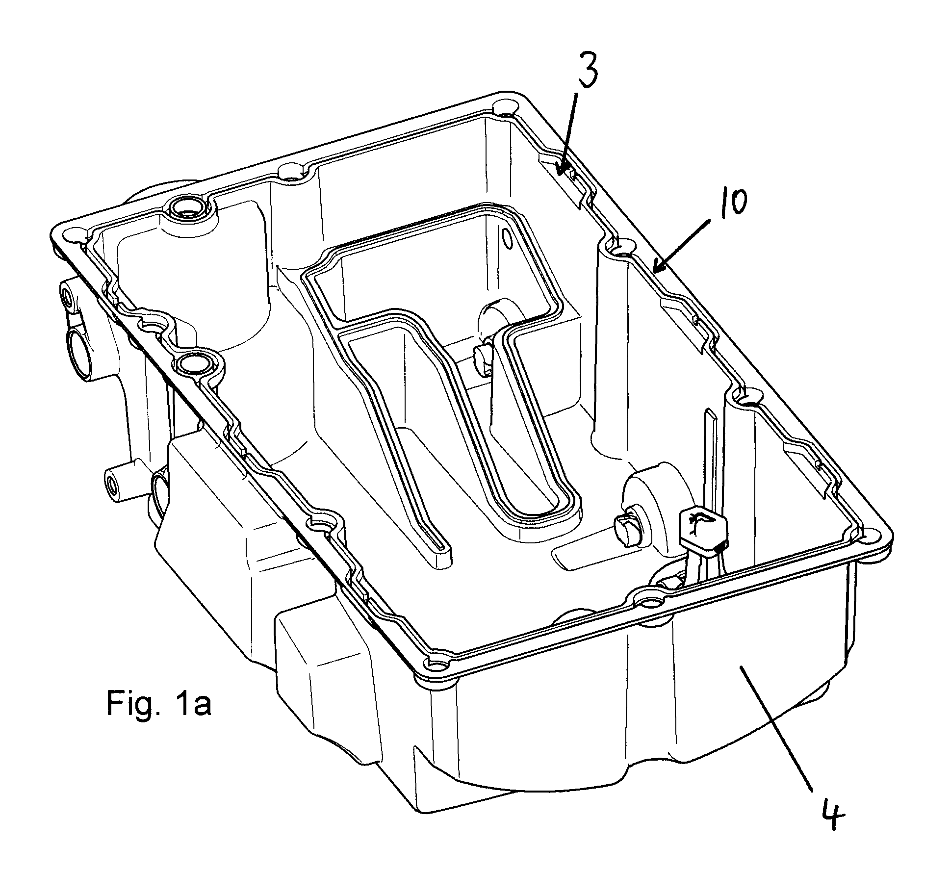
[0024]FIG. 1 illustrates an oil pan baffle 1 positioned with contact or support surfaces 2 in receptacles 3 of an oil pan 4. A securing device 5 embodied as an oil pan gasket having a gasket body 6 and securing elements 7 projecting inwardly from in inner perimeter of the gasket body 6 is arranged on the oil pan 3.
[0025]As can be seen especially in the detail view of FIG. 2, the securing elements 7 are an integral or monolithic part of the gasket and are made of the same material as the oil pan gasket. Oil pan gaskets and the (elastic) material used for their manufacture are well known in the art and need not be discussed here.
[0026]FIG. 2 shows that the securing elements 7 integrated into the oil pan gasket rest on the contact surfaces 2 of the oil pan baffle 1 in the receptacles 3. In this way, the securing elements 7 clamp the oil pan baffle 1, that has been placed into the oil pan 4 prior to installing the securing device 5, by their elastic properties in the receptacles 3 of the oil pan 4. The securing elements 7 in this way provide an initial transport safety means that provides a transport securing action for the oil pan baffle 1 on the oil pan for transport to the site of final assembly.
[0027]As an alternative to the disclosed concept of securing the oil pan baffle 1 for transport by means of the securing device 5 to be installed on the oil pan 4 after the oil pan baffle 1 has been positioned thereon, it is possible to fasten the securing device 5 on the oil pan baffle 1 either by fastening means or by vulcanizing the securing elements 7 of the securing device 5 on the oil pan baffle 1.
[0028]FIG. 3 shows a schematic section view of the oil pan 4 and the oil pan baffle 1 as well as the crankcase 8 in aligned position before mounting in the indicated assembly direction 9. The securing device 5 is arranged in the gasket groove 10 of the oil pan 4 and is still in its initial uncompressed state. The securing element 7 rests on the contact surface 2 of the oil pan baffle 1 arranged in the receptacle 3 of the oil pan 4.
[0029]The illustration of FIG. 3 shows the securing element 7 in contact with the contact surface 2 of the oil pan baffle. This contact can be a clamping contact when installing the oil pan baffle 1 first and later arranging the securing device 5 with securing elements 7 thereon, but it can also be understood as the securing elements 7 being vulcanized to the contact surfaces 2 of the oil pan baffle 1 which means that the oil pan baffle 1 and the securing device form a unit and are installed together on the oil pan 4.
[0030]FIG. 4 shows the oil pan 4 being fastened to the crankcase 8. The fasteners that fasten the oil pan force the elastic securing device 5 into the gasket groove 10 and also compress the securing device 5 in the form of the gasket for proper sealing of the oil pan relative to the crankcase. At the same time, the securing element 7 also presses down on the oil pan baffle in the area of the contact surface 2 and forces the oil pan baffle 1 tightly against the receptacle 3 of the oil pan 4. In this way the oil pan baffle 1 is fixedly secured between the oil pan 4 and the crankcase 8 in the same mounting step that secures the oil pan 4 on the crankcase 8.
[0031]The securing device 5 secures the oil pan baffle 1 without allowing any play once the oil pan 4 is mounted on the crankcase or engine. The oil pan baffle 1 is seated tightly and secured fixedly on the oil pan. No additional fastening elements (such as screws) are required; no additional assembly time is required for inserting and tightening such fastening elements.
[0032]Even when the contact surface or the oil pan under operating conditions will relax to some degree or different thermal expansion coefficients cause play between the components, the securing device 5 according to the invention will compensate any fluctuations.
[0033]It is possible to secure the oil pan baffle by means of clip-on devices on the oil pan. In this situation, the above described clamping action provided by the securing device 5 with the securing elements 7 upon mounting the oil pan is desirable for acoustic reasons.
[0034]In order to avoid the extra mounting step mentioned in the beginning, the oil pan baffle can also be welded to the receptacles of the oil pan; in this case the securing device 5 with securing elements 7 is not required for securing the oil pan baffle 1.
[0035]While specific embodiments of the invention have been shown and described in detail to illustrate the inventive principles, it will be understood that the invention may be embodied otherwise without departing from such principles.

PUM

no PUM

Description & Claims & Application Information

We can also present the details of the Description, Claims and Application information to help users get a comprehensive understanding of the technical details of the patent, such as background art, summary of invention, brief description of drawings, description of embodiments, and other original content. On the other hand, users can also determine the specific scope of protection of the technology through the list of claims; as well as understand the changes in the life cycle of the technology with the presentation of the patent timeline. Login to view more.

Similar technology patents

Blind Nut and Mounting Structure Thereof

InactiveUS20180038406A1decrease heighteasily mount
Owner:NEWFREY

Dish washer

InactiveUS20090050184A1easily mount
Owner:LG ELECTRONICS INC

Watch

ActiveUS20060193209A1readily and easilyeasily mount
Owner:SEIKO INSTR INC

Classification and recommendation of technical efficacy words

  • easily mount

Apparatus and method for receiving tag signal in mobile RFID reader

InactiveUS20070069864A1easily mount
Owner:ELECTRONICS & TELECOMM RES INST

Tiled display rotational assembly

ActiveUS20130269882A1easily mount
Owner:CHRISTIE DIGITAL SYST USA INC

Commodity Splitter for an Air Delivery System

ActiveUS20110311322A1streamline in appearanceeasily mount
Owner:DEERE & CO

Multilayer capacitor

ActiveUS7088569B1lower inductanceeasily mount
Owner:TDK CORPARATION

Energy saving lamp with sensor

InactiveUS20060261741A1improve convenienceeasily mount
Owner:HWANG YOON KYU
Why Eureka
Try Eureka