Automatic flashing brake lights and associated method

a technology of automatic flashing and brake lights, applied in the direction of signalling/lighting devices, vehicle components, optical signalling, etc., can solve the problems of more injuries and property damage, the blending of brake lights and other lights at nighttime can become difficult to distinguish, and the problem is further intensified

Inactive Publication Date: 2010-03-18
KIM PETER P
View PDF8 Cites 16 Cited by
  • Summary
  • Abstract
  • Description
  • Claims
  • Application Information

AI Technical Summary

Benefits of technology

[0020]There has thus been outlined, rather broadly, the more important features of the invention in order that the detailed description thereof that follows may be better understood, and in order that the present contribution to the art may be better appreciated. There are additional features of the invention that will be described hereinafter and which will form the subject matter of the claims appended hereto.
[0021]It is noted the purpose of the foregoing abstract is to enable the U.S

Problems solved by technology

The National Highway Traffic Safety Administration (NHTSA) reported that rear-impact collisions result in more injuries and property damage than any other type of automobile accident.
The blending of brake lights and other lights at nighttime can become difficult to differentiate.
This problem is further intensified under adverse weather conditions (rain, fog, etc).

Method used


Image

  • Automatic flashing brake lights and associated method
  • Automatic flashing brake lights and associated method
  • Automatic flashing brake lights and associated method

Examples


first embodiment

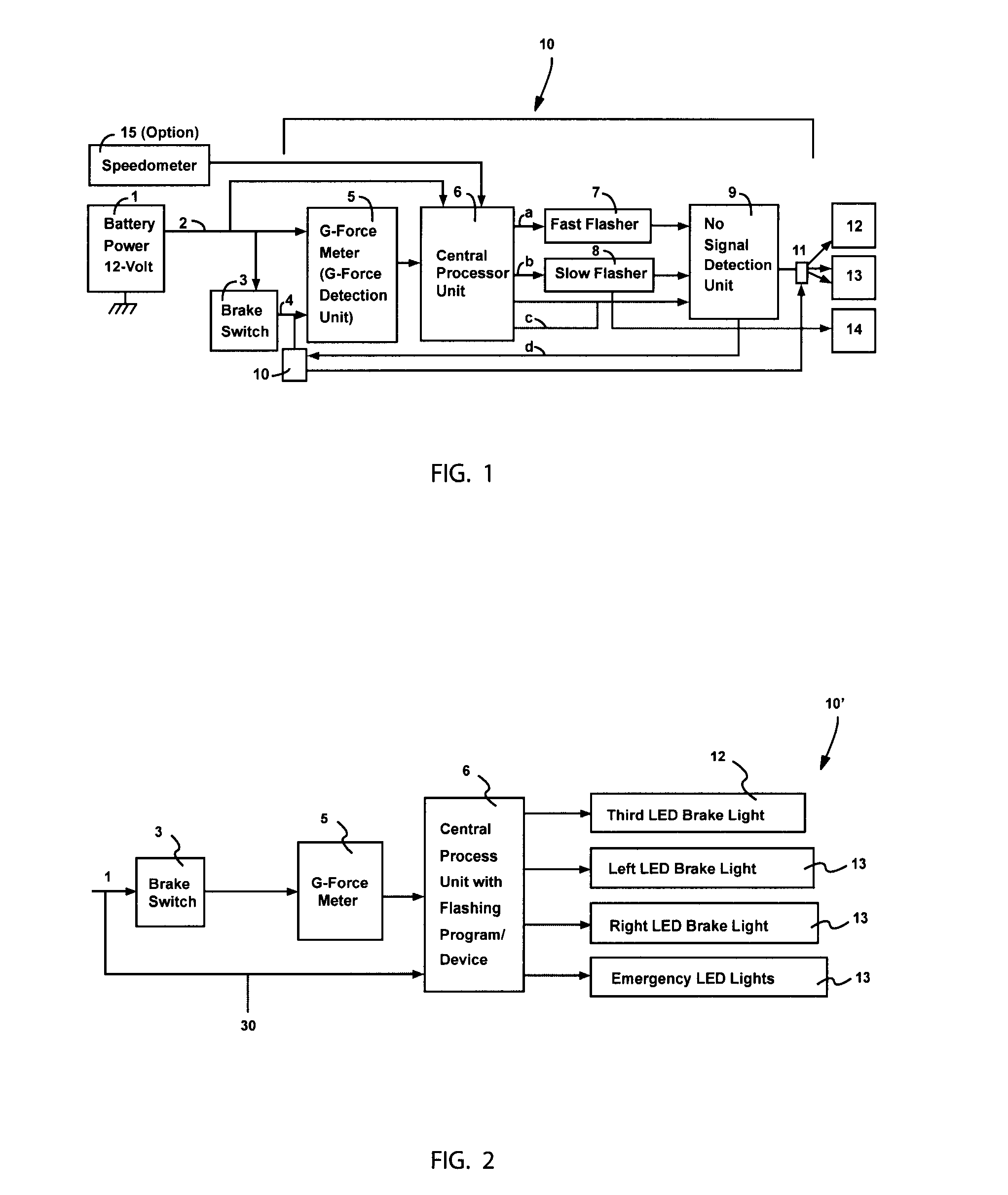
[0031]Referring initially to FIG. 1, a schematic diagram of the first embodiment is illustrated as including a 12-volt battery power supply source 1 electrically coupled to a 12-volt power line 2 when the car ignition switch is on. As long as the car ignition switch is on, the AFBL has a constant supply of 12-volt. Brake switch 3 is communicatively coupled to a G-force meter 5 via brake power line 2. In this manner, as a driver pushes down a brake pedal (not shown), a 12-volt brake power signal is transmitted to G-force meter 5. As brake pressure is applied to the brake pedal, digitalized G-Force meter 5 is activated and reads out the G-force value. The combination of such claimed elements solves the problem of generating false or premature G-force values when the vehicle swerves or switches gears abruptly, without actually braking, and thereby provides an unpredictable and unexpected result which is not rendered obvious by one skilled in the art because it calculates the G-force va...

second embodiment

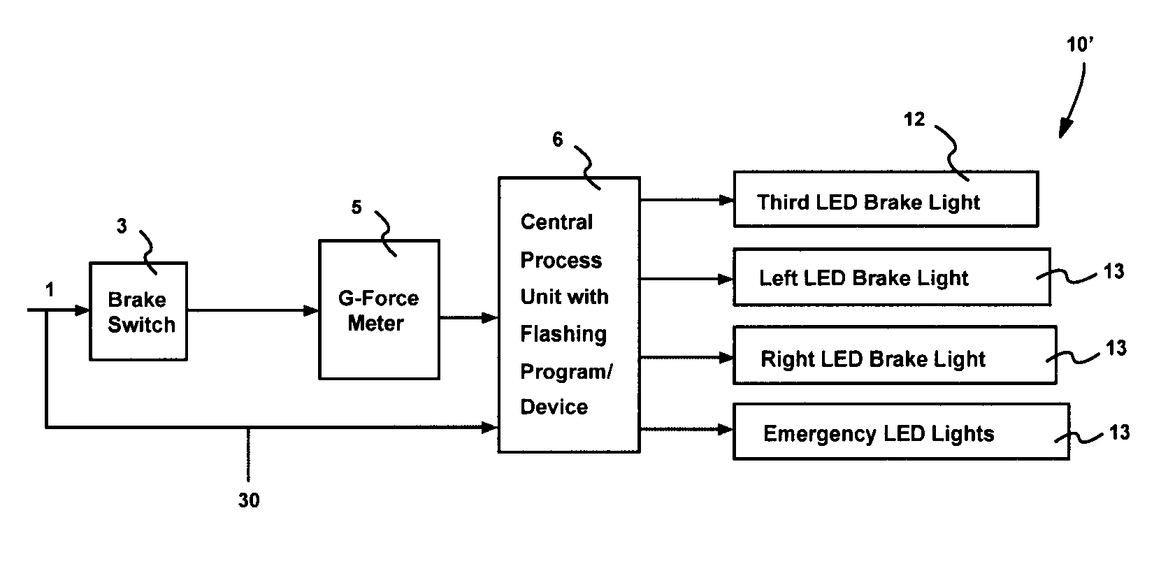
[0040]Now referring to FIG. 2, a schematic diagram of the second embodiment is illustrated as including a 12-Volt power line 1 when the ignition switch is on, which is connected to brake switch 3. As the brake pedal is applied, a brake signal power goes into the G-force meter 5. According to the different G-force value this meter feeds its readings into the central processor unit 6. According to the different G-force reading, the processor 6 transmits different signals to different light units 12-14.

[0041]Such a central processor unit 6 may include a flashing program associated with each different light unit 12-14 such that flasher devices 7, 8 are not necessary. The combination of such claimed elements solves the problem of not knowing the rate of vehicle deceleration and thereby provides an unpredictable and unexpected result which is not rendered obvious by one skilled in the art because it flashes the vehicle brake lights are different frequencies and time periods commensurate w...


PUM


Abstract

An automatic vehicle brake light flashing system for identifying an extremity of a vehicle braking force includes a plurality of brake lights connected to a G-force meter. A power supply source transmits a brake power signal to the G-force meter only when the brake switch is activated during vehicle braking procedures. The G-force meter determines a G-force value inside the vehicle only upon receiving the brake power signal. A processor generates and transmits corresponding brake light signals to the brake lights so that the brake lights are caused to flash at different frequencies upon automatically receiving the corresponding brake light signals. Such frequencies may include: fast flashing brake lights for hand force braking / sudden stopping; moderately slow flashing brake light for medium force braking; regular solid brake light for light braking; and contestant emergency warning flashing lights for front and rear end collisions.

Description

CROSS REFERENCE TO RELATED APPLICATIONS[0001]This application claims the benefit of U.S. Provisional Application No. 61 / 192,216, filed Sep. 16, 2008, the entire disclosures of which are incorporated herein by reference.STATEMENT REGARDING FEDERALLY SPONSORED RESEARCH OR DEVELOPMENT[0002]Not Applicable.REFERENCE TO A MICROFICHE APPENDIX[0003]Not Applicable.BACKGROUND OF THE INVENTION[0004]1. Technical Field[0005]This invention relates to a brake light system for vehicles and, more particularly, to a flashing brake light system that utilizes a G-force meter unit, central processor unit, fast rate flasher, slow rate flasher, no signal detection unit, several relay systems, and communication links for flashing vehicle brake lights in alternate patterns.[0006]2. Prior Art[0007]The National Highway Traffic Safety Administration (NHTSA) reported that rear-impact collisions result in more injuries and property damage than any other type of automobile accident. Over 2.5 million rear-impact c...

Claims


Application Information

Patent Timeline
IPC IPC(8): B60Q1/44
CPCB60Q1/447
Inventor KIM, PETER P.
Owner KIM PETER P
Why Eureka
Try Eureka