
Liquid crystal display and method thereof

Active Publication Date: 2010-03-18
SAMSUNG DISPLAY CO LTD
View PDF12 Cites 22 Cited by
  • Summary
  • Abstract
  • Description
  • Claims
  • Application Information

AI Technical Summary

Benefits of technology

[0010]It has been determined herein, according to the present invention, that in the conventional method of applying the same voltage to two sub-pixels and dropping the voltage of one sub-pixel by using a separate switching element, since the conventional liquid crystal display (“LCD”) should be provided with a plurality of signal lines and a plurality of contact holes, the aperture ratio is low. Furthermore, it has been determined herein that when the number of gate lines among the signal lines increases in a conventional LCD, the charging time of each pixel reduces. Moreover, the charging time of each pixel in a conventional LCD further reduces during high driving.
[0011]The present invention has been made in an effort to provide an LCD for adjusting different voltages of two sub-pixels while ensuring an aperture ratio. Furthermore, the present invention provides an LCD for sufficiently ensuring a charging time of pixels. The present invention also provides a method of reducing an aperture ratio in an LCD that charges different voltages in its sub-pixels.
[0026]Another exemplary embodiment of the present invention provides a method of improving an aperture ratio of an LCD, the LCD having sub-pixels which are charged with different voltages, the method including sequentially arranging first, second, and third pixels adjacent to one another in a column direction, connecting a first gate line to each of the second and third pixels in common, connecting a capacitance electrode line to each of the first and second pixels in common, connecting a first data line to the second pixel, and connecting a second data line to the first and third pixels.
[0027]According to this configuration, it is possible to ensure an aperture ratio while differently adjusting the voltage of two sub-pixels. In addition, even in the case of performing high driving, it is possible to sufficiently ensure the charging time of the pixels.

Problems solved by technology

Moreover, the charging time of each pixel in a conventional LCD further reduces during high driving.

Method used


Image

  • Liquid crystal display and method thereof
  • Liquid crystal display and method thereof
  • Liquid crystal display and method thereof

Examples


Embodiment Construction

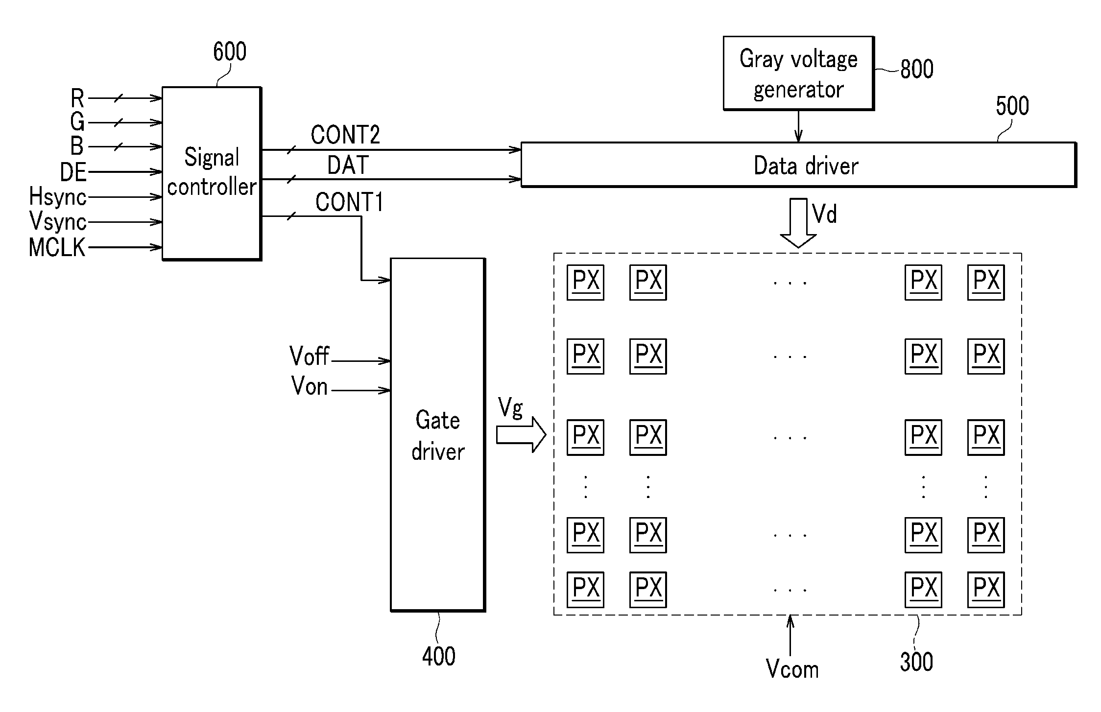
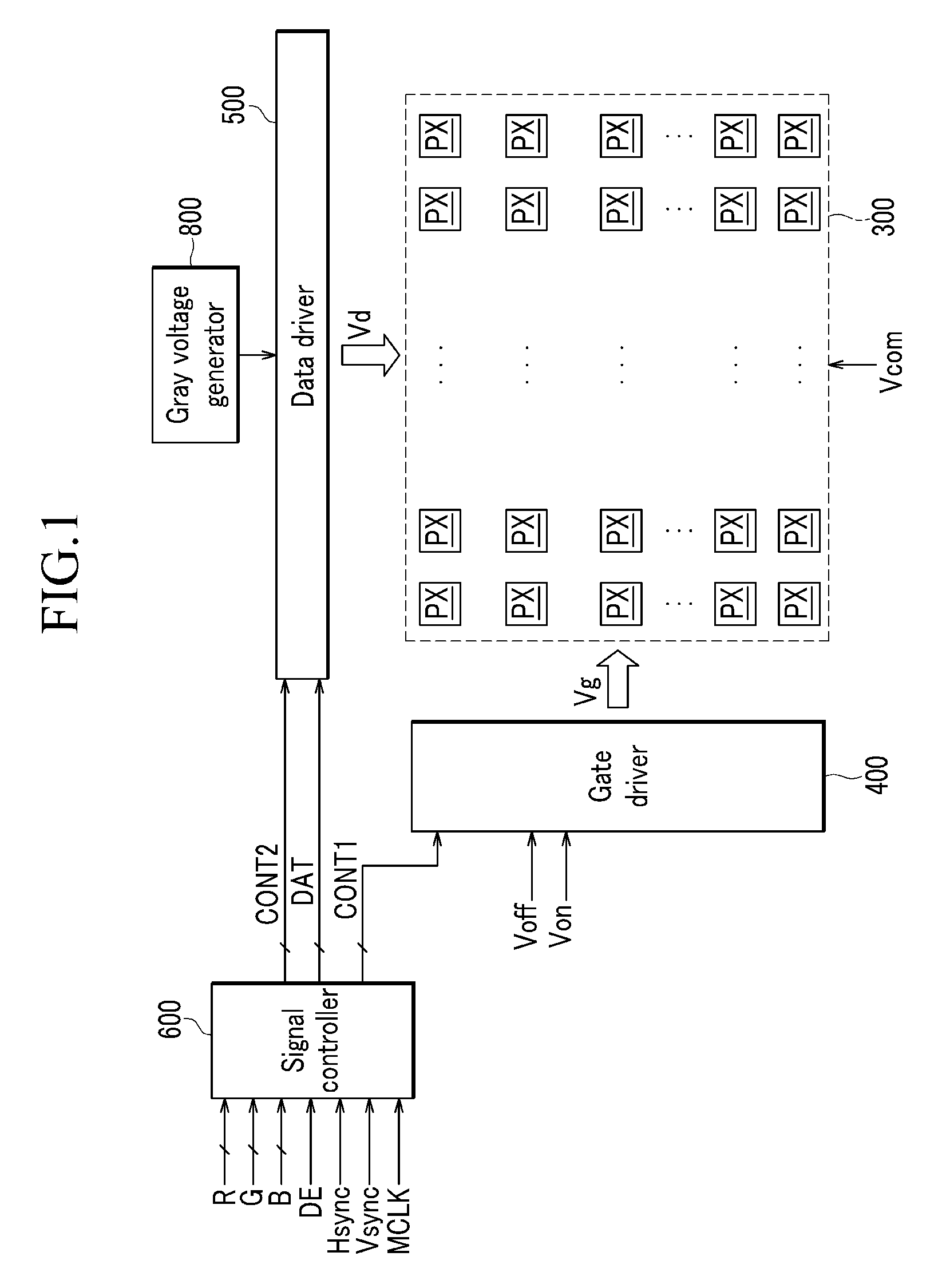
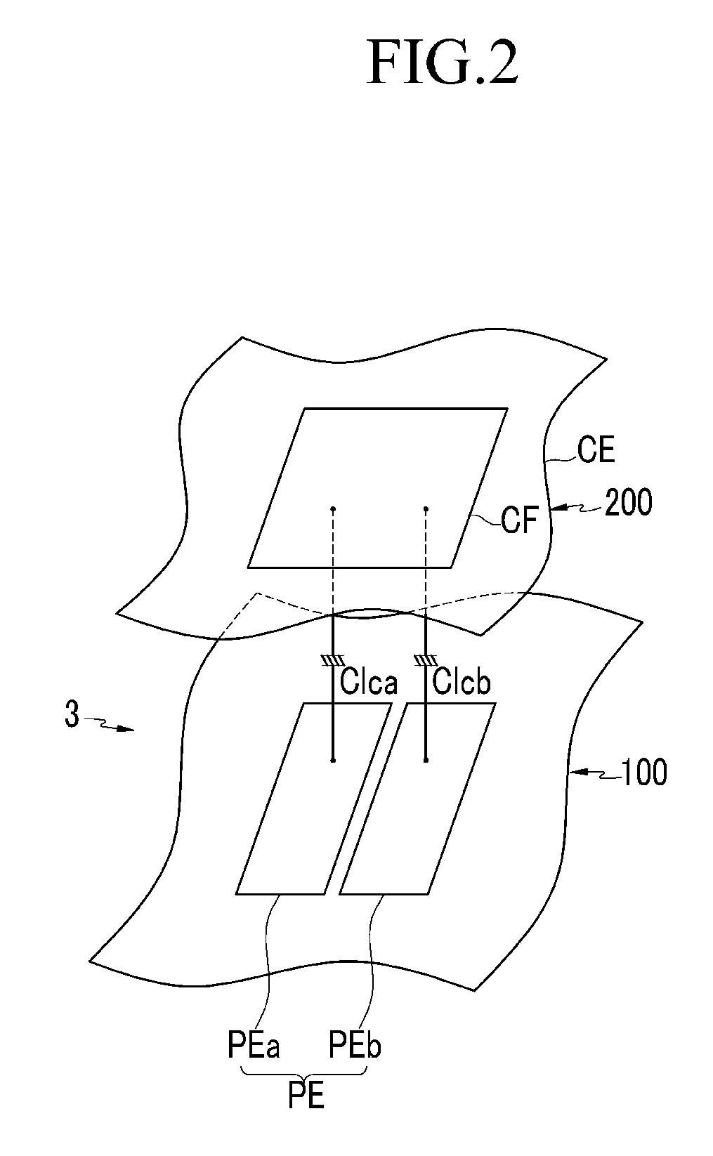
[0038]The present invention will be described more fully hereinafter with reference to the accompanying drawings, in which exemplary embodiments of the invention are shown. As those skilled in the art would realize, the described embodiments may be modified in various different ways, all without departing from the spirit or scope of the present invention.

[0039]In the drawings, the thickness of layers, films, panels, regions, etc., are exaggerated for clarity. Like reference numerals designate like elements throughout the specification. It will be understood that when an element such as a layer, film, region, or substrate is referred to as being “on” another element, it can be directly on the other element or intervening elements may also be present. In contrast, when an element is referred to as being “directly on” another element, there are no intervening elements present.

[0040]It will be understood that, although the terms first, second, third etc. may be used herein to describe v...


PUM


Abstract

A liquid crystal display (“LCD”) has first, second, and third pixels adjacent to one another in a column direction. The LCD includes a first gate line connected to each of the second and third pixels in common, a capacitance electrode line connected to each of the first and second pixels in common, a first data line connected to the second pixel, and a second data line connected to the first and third pixels.

Description

[0001]This application claims priority to Korean Patent Application No. 10-2008-0091658, filed on Sep. 18, 2008, and all the benefits accruing therefrom under 35 U.S.C. §119, the contents of which in its entirety are herein incorporated by reference.BACKGROUND OF THE INVENTION[0002](a) Field of the Invention[0003]The present invention relates to a liquid crystal display (“LCD”) and method thereof. More particularly, the present invention relates to an LCD that can adjust different voltages of sub-pixels while ensuring an aperture ratio, and a method of improving an aperture ratio of the LCD.[0004](b) Description of the Related Art[0005]A liquid crystal display (“LCD”) is one of the most widely used flat panel displays. The LCD includes two display panels provided with electric field generating electrodes, such as pixel electrodes and a common electrode, and a liquid crystal layer interposed between the two display panels. In the LCD, voltages are applied to the electric field genera...

Claims


Application Information

Patent Timeline
IPC IPC(8): G09G3/36
CPCG02F1/136213G02F2001/134345G09G3/3659G09G3/3677G09G2300/0426G09G3/3688G09G2300/0842G09G2300/0852G09G2310/0205G09G2320/028G09G2300/0443G02F1/134345G02F1/133G02F1/1343
Inventor KIM, YOON-JANGLEE, SEONG-YOUNGKWON, YEONG-KEUNPARK, KEE-BUMPARK, KYUNG-HO
Owner SAMSUNG DISPLAY CO LTD
Learn More