Thermal print head

a printing head and thermal technology, applied in printing and other directions, can solve the problem of exposed inner layer, and achieve the effect of inhibiting the occurrence of sticking phenomenon

Inactive Publication Date: 2010-03-18
ROHM CO LTD
View PDF7 Cites 3 Cited by
  • Summary
  • Abstract
  • Description
  • Claims
  • Application Information

AI Technical Summary

Benefits of technology

[0005]The present invention has been proposed under the above-described circumstances. It is therefore an object of the

Problems solved by technology

While the thermal print head is being used for a long period, the

Method used


Image

  • Thermal print head
  • Thermal print head
  • Thermal print head

Examples


Embodiment Construction

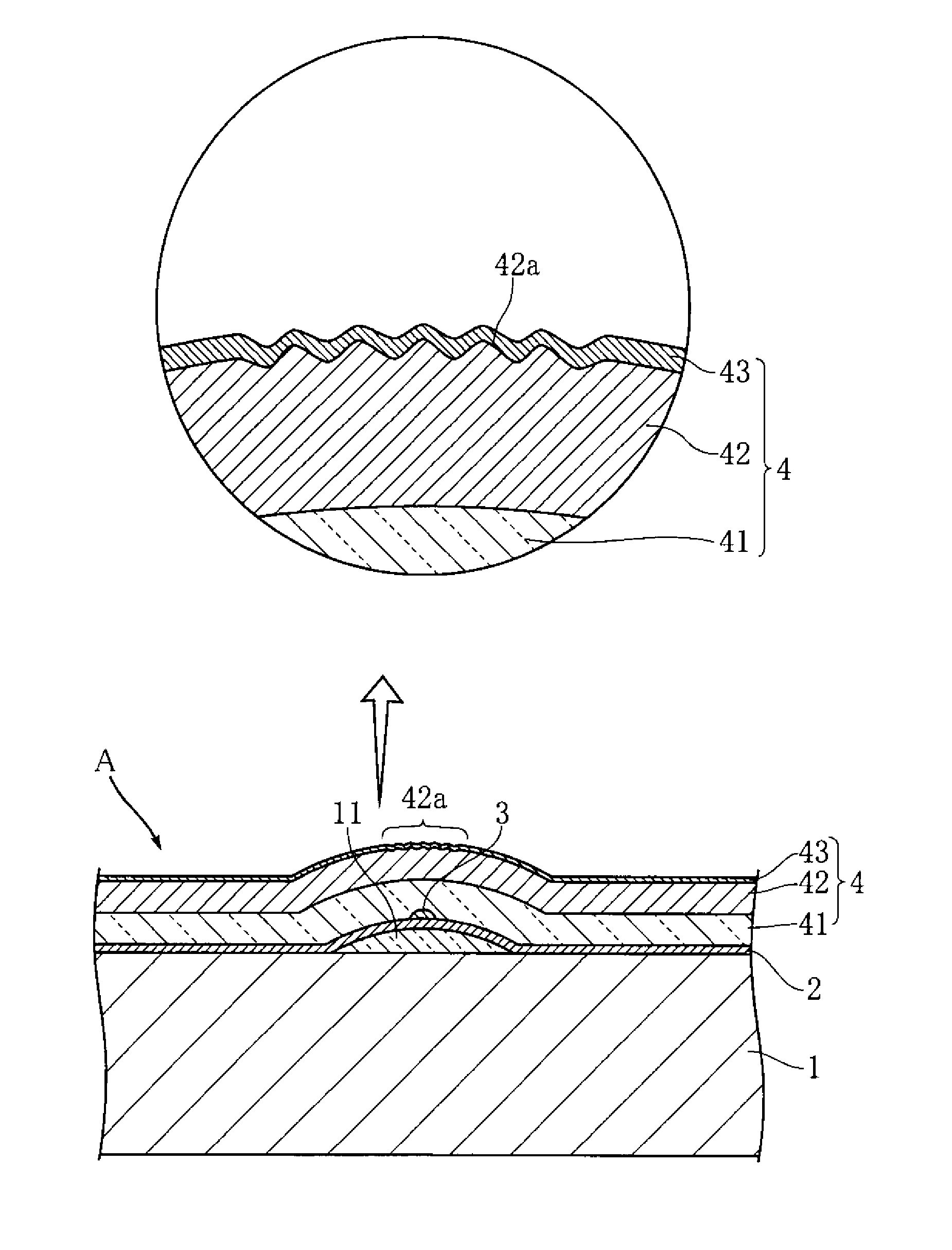
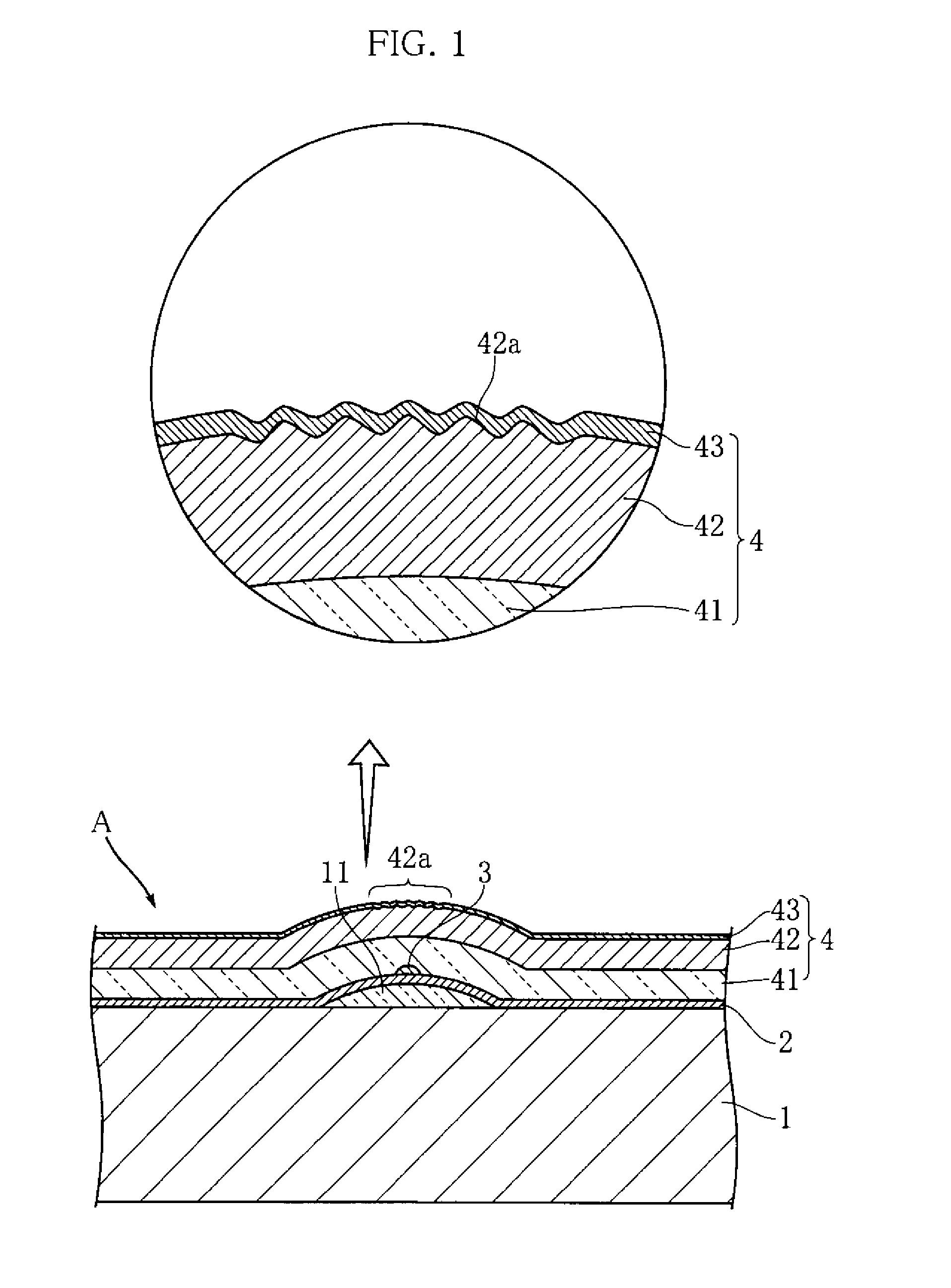
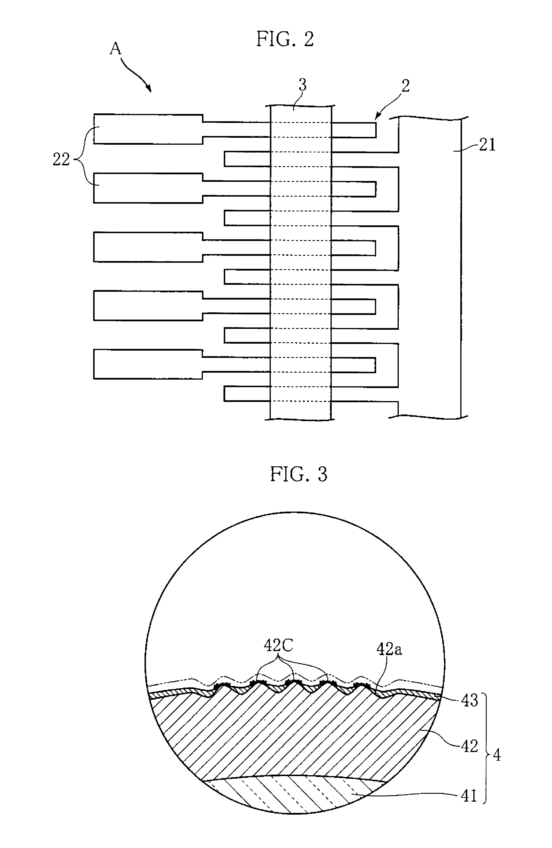
[0014]FIG. 1 and FIG. 2 show an example of a thermal print head according to the present invention. The illustrated thermal print head A includes a substrate 1, an electrode pattern 2, a heat generating resistor 3 and a protective layer 4. Only the electrode pattern 2 and the heat generating resistor 3 are depicted in FIG. 2 for easier understanding.

[0015]The substrate 1 is an insulated substrate in the shape of an elongate rectangle in a plan view extending in a primary scanning direction, and is made of an alumina ceramic, for example. As shown in FIG. 1, a partial glaze 11 is formed at the upper surface of the substrate 1. The partial glaze 11 is in the shape of an elongate strip extending in the primary scanning direction. The cross section of the partial glaze 11 bulges toward the thickness direction of the substrate 1 (upward in FIG. 1).

[0016]The electrode pattern 2 is for applying current to the heat generating resistor 3, and includes a common electrode 21 and a plurality of...


PUM


Abstract

A thermal print head A includes a substrate 1, a heat generating resistor 3 supported by the substrate 1, and a protective layer 4 which covers the heat generating resistor 3. The protective layer 4 includes a first inner layer 41 which is in contact with the heat generating resistor 3, a second inner layer 42 formed on the first inner layer 41, and an outer layer 43. Part of the second inner layer 42 is formed as a rough surface 42a which has a surface roughness of Ra 0.1 through 0.3. The rough surface 42a is disposed at a position corresponding to the heat generating resistor 3. The outer layer 43 is made of a metal nitride or a chemical compound containing a metal nitride, and has a thickness of 0.1 through 0.5 μm.

Description

TECHNICAL FIELD[0001]The present invention relates to a thermal print head used in a thermal printer.BACKGROUND ART[0002]A thermal print head is a device for printing images or characters by locally heating a printing object such as thermal paper (see Patent Document 1, for example). FIG. 4 shows an example of a conventional thermal print head. In the illustrated thermal print head X, an electrode 93 is disposed on a substrate 91 formed with a partial glaze 92, and part of the electrode extends in the secondary scanning direction. A heat-generating resistor 94, crossing the electrode 93, is formed to extend in the primary scanning direction. The heat generating resistor 94 is covered by a protective layer 95. Current is applied to the heat generating resistor 94 via the electrode 93 while the thermal paper, pressed onto the protective layer 95, is moved in the secondary scanning direction. The current application causes the heat generating resistor 94 to generate heat, whereby desir...

Claims


Application Information

Patent Timeline
IPC IPC(8): B41J2/335
CPCB41J2/33515B41J2/33525B41J2/3355B41J2/33535B41J2/3353
Inventor YAMADE, TAKUMIKANEI, NAOFUMI
Owner ROHM CO LTD
Why Eureka
Try Eureka