

Display Device with Low Scratch Visibility and Manufacturing Method Thereof
- Summary
- Abstract
- Description
- Claims
- Application Information
AI Technical Summary
Benefits of technology
Problems solved by technology
Method used
Image

Examples
Embodiment Construction
[0031]The present invention relates to a display device. In a preferred embodiment, the display device of this invention is a liquid crystal display device including home LCD televisions, LCD monitors of personal computers and laptop computers, LCD screens of mobile phones and digital cameras, and LCD devices used in other electronic products.
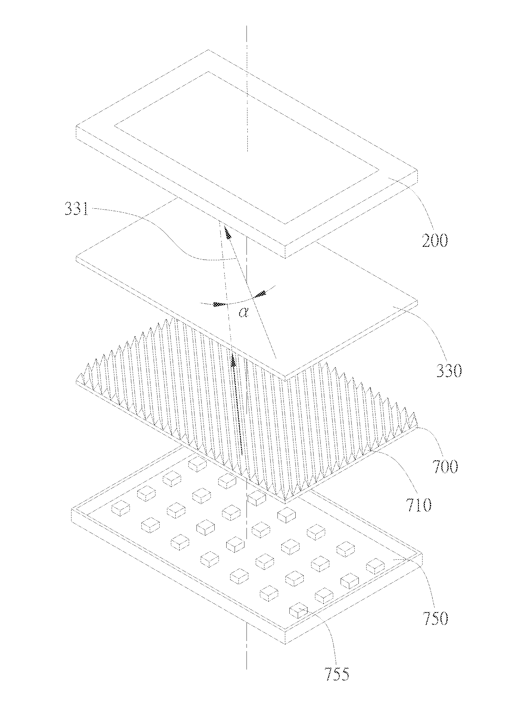
[0032]In the embodiment illustrated by FIG. 2, the display device includes a backlight module 100 and a display panel 200. The display panel 200 is disposed on the backlight module 100 with its back side corresponding to the light output side of the backlight module 100. Light output from the backlight module 100 enters the display panel 200 to facilitate the image display on the display surface 210 of the display panel 200.
[0033]As illustrated by FIG. 2, the backlight module 100 includes a light guide 130, a light source 150, and a plurality of optical films 170. The light guide 130 can be a rectangle or an irregular polygon having two adjacen...
PUM
 Abstract
Description
Claims
Application Information