Pluggable system between optical transceiver and host system

a technology of optical transceiver and host system, which is applied in the direction of optical elements, coupling device connections, instruments, etc., can solve the problems of reducing the transmission speed of the transceiver and the host device, and increasing the number of electrodes in the connector and the plug. , to achieve the effect of reliable and precise, increasing the transmission speed

Active Publication Date: 2010-03-18
SUMITOMO ELECTRIC IND LTD
View PDF7 Cites 38 Cited by
  • Summary
  • Abstract
  • Description
  • Claims
  • Application Information

AI Technical Summary

Benefits of technology

[0011]A new type of the optical transceiver has a plurality of, for instance, more than hundreds (100) electrodes to communicate with the host system. Moreover, the communication between the optical transceiver and the host system increases the transmission speed, often exceeds 10 Gbps. Accordingly, the electrodes in the connector, also in the plug, forced to be downsized, which results in the reliable and precise mechanism to set the pluggable optical transceiver in the host system. In the present invention, the optical transceiver is directly set to respect to the rail, not to the face panel of the host system, and the connector is rigidly and reliably aligned with the rail; accordingly, the electrical plug in the optical transceiver may be precisely and reliable mated with the connector in the host system.

Problems solved by technology

Even in new standards, the communication between the transceiver and the host device is limited in the speed thereof to 10 Gbps because of the electrical mismatching of the transmission impedance at the electrical connector and the plug.
Moreover, greater power consumption is necessary for the electronic components in the transceiver to process such high speed signals and more ground patterns are also necessary to suppress the waveform degradation.
These critical conditions result in the increase of the number of the electrode in the connector and the plug.
In another aspect of the electronic equipment, because a smaller sized housing is permanently requested in the field, it is not allowable solution to enlarge the size of the housing as the increase of the number of the electrode.

Method used


Image

  • Pluggable system between optical transceiver and host system
  • Pluggable system between optical transceiver and host system
  • Pluggable system between optical transceiver and host system

Examples


Embodiment Construction

[0027]Next, preferred embodiments of the present invention will be described as referring to accompanying drawings.

[0028]The pluggable optical transceiver has been developed as following: the outer shape / dimensions and the electrical characteristics have been ruled in the standards called as the multi-source-agreements (MSA). Typical MSA is, what is called, the small form-factor pluggable (SFP) standard. An optical transceiver with a function to be operated around 10 Gbps is already arranged in the MSA. Various manufacturers are currently going to arrange a new standard for transceivers operable over 10 Gbps, namely, 40 Gbps and 100 Gbps. Transceivers following the already established standards are called as, for instance, SFP, XFP, X2, and something like that, but the standard for a transceiver operable at 100 Gbps will be called as “Century FP” (CFP transceiver). We hereafter call the transceiver according to the present application as CFP transceiver.

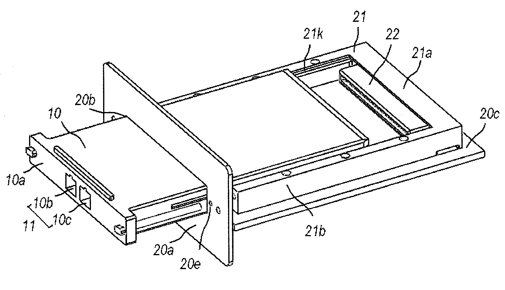
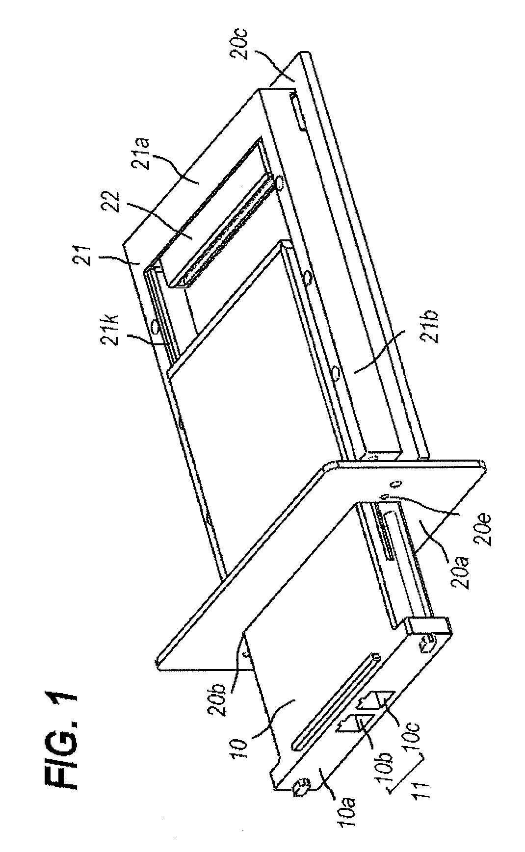
[0029]FIG. 1 schematically il...


PUM


Abstract

A mechanism to fix the new type of the pluggable optical transceiver to the host system is disclosed. The optical transceiver provides the screws, while, the host system has the face panel with a port and the rail system between which the optical transceiver is set through the port. In the present invention, the screw of the transceiver is fastened to the rail not the face panel, and the rail is precisely aligned with the electrical connector. Thus, the pluggable transceiver in the electrical plug thereof is exactly mated with the electrical connector of the host system.

Description

CROSS REFERENCE TO RELATED APPLICATION[0001]This application claims priority to U.S. Provisional Patent Application Ser. No. 61 / 098,093, filed on Sep. 18, 2008, which is incorporated herein by reference in its entirety.BACKGROUND OF THE INVENTION[0002]1. Field of the Invention[0003]The present invention relates to a pluggable optical transceiver used in an arrangement that, inserting into a rail or a cage prepared on a host board, the electrical plug implemented in a rear end thereof mates with the electrical connector set in the deep end of the rail or the connector.[0004]2. Related Prior Art[0005]Various prior documents have been disclosed a pluggable system between the host equipment and the optical transceiver, such as US-2004081418A, US-20070133930A and US-20070110374A. The installation of the pluggable transceiver on the host device was accomplished by setting the pluggable transceiver in the cage or the rail they were prepared in the host device. The optical transceiver provi...

Claims


Application Information

Patent Timeline
Patent Type & Authority Applications(United States)
IPC IPC(8): G02B6/36
CPCG02B6/4246H01R13/748H01R13/631
Inventor OKI, KAZUSHIGE
Owner SUMITOMO ELECTRIC IND LTD
Why Eureka
Try Eureka