Poke-in connector

Inactive Publication Date: 2010-03-18
TE CONNECTIVITY CORP
View PDF7 Cites 21 Cited by
  • Summary
  • Abstract
  • Description
  • Claims
  • Application Information

AI Technical Summary

Benefits of technology

[0006]An advantage of the present invention is that the connector includes a poke-in contact that provides a quick and easy connection to a wire, cable or other electrical device.
[0007]Another advantage of the present invention is that the connector does not require fasteners to secure to a substrate or surface.
[0008]Yet another advantage of the present invention is that the connector housing is manufactured by an injection molding process, thereby reducing manufacturing costs.

Problems solved by technology

However, these types of connectors require the use of tools and / or complex methods to initiate and secure the connection.
The use of tools and / or complex methods to make the connection is time consuming, as well as expensive.
Further, these types of connections are often permanent and may prevent the replacement of any other components at a later time.

Method used


Image

  • Poke-in connector
  • Poke-in connector
  • Poke-in connector

Examples


Embodiment Construction

[0030]The present invention will now be described more fully hereinafter with reference to the accompanying drawings in which preferred embodiments of the invention are shown. This invention may, however, be embodied in many different forms and should not be construed as limited to the embodiments set forth herein; rather, these embodiments are provided so that this disclosure will be thorough and complete and will fully convey the scope of the invention to those skilled in the art.

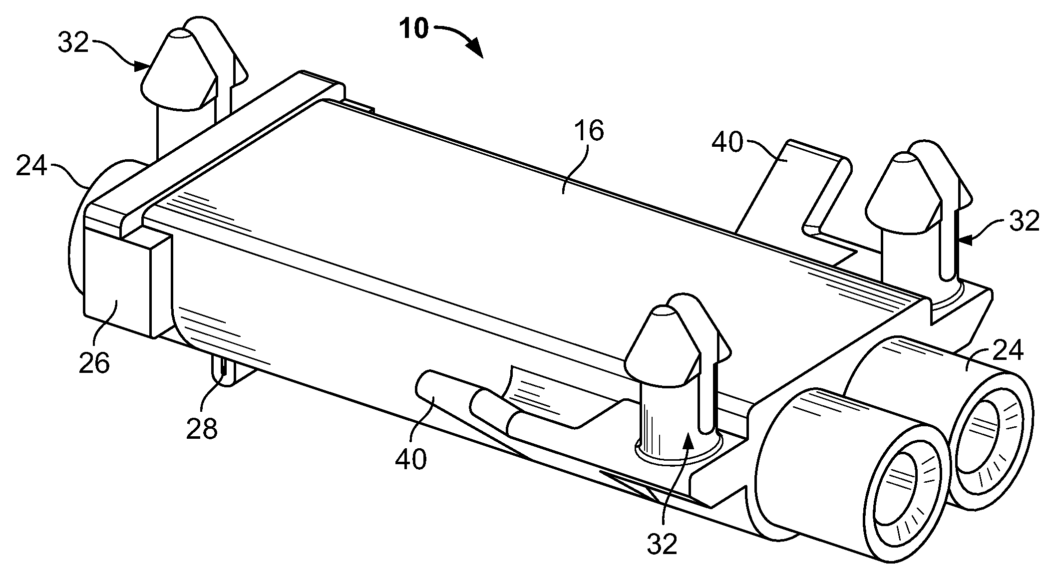
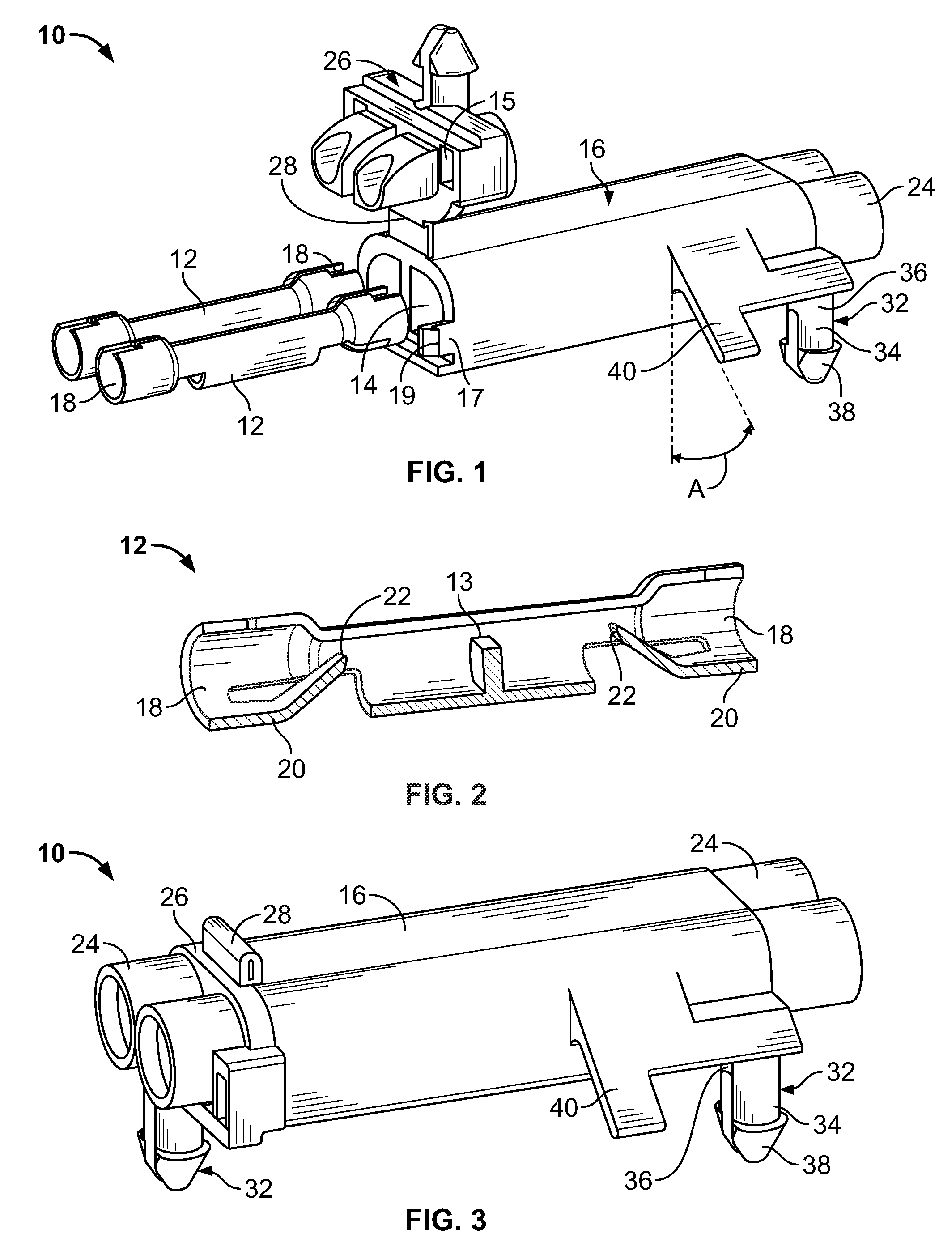
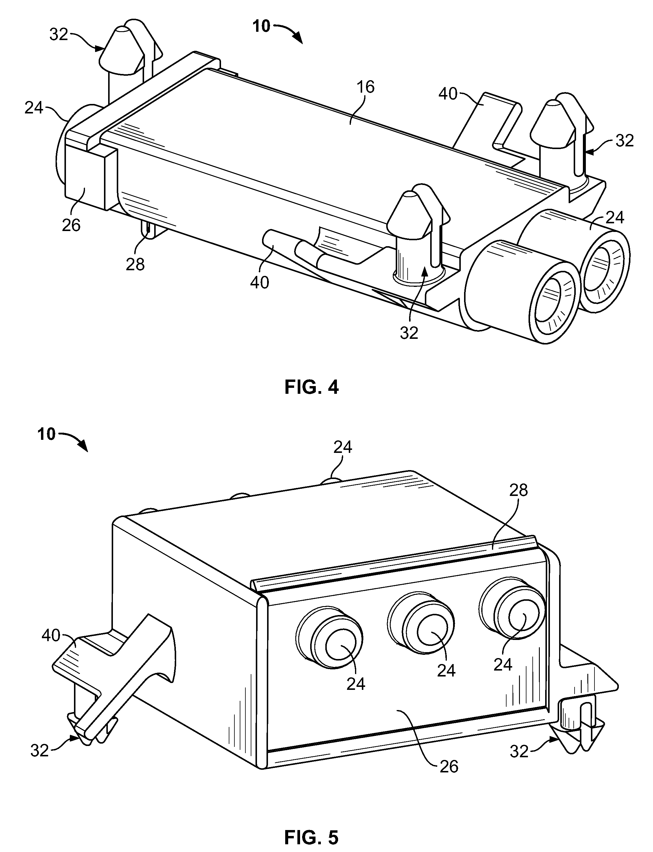
[0031]Referring to FIGS. 1, 2, 3 and 4, an exemplary embodiment of a poke-in connector (hereinafter referred to as “connector”) 10 is shown. Connector 10 includes a housing 16 and a contact 12. Housing 16 includes a cavity 14 for receiving contact 12. Housing 16 may be formed by an injection molding process, or any other suitable process used to manufacture a non-conductive material, such as plastic. Housing 16 may have a generally rectangular configuration or any other suitable configuration to receive a...


PUM


Abstract

A connector having a housing and a contact are described. The connector includes an electrically conductive contact and a housing. The housing has a cavity to receive and secure the contact, a first alignment feature for receiving a first conductive cable into the contact and a second alignment feature for receiving a second conductive cable into the contact. The housing also includes at least one attachment point protruding from the housing to attach and secure the connector to a surface and at least one flexible flange to substantially prevent movement of the connector on a surface. The contact receives and secures the first conductive cable and the second conductive cable to provide an electrical connection between the first conductive cable and the second conductive cable. The attachment point attaches and secures the connector to a surface.

Description

FIELD OF THE INVENTION[0001]The present invention is directed to a poke-in style connector. More specifically, the present invention is directed to a poke-in style connector having an attachment feature that can snap into a substrate or surface.BACKGROUND OF THE INVENTION[0002]Electrical applications may require the use of electrical connectors to form electrical connections between various electrical devices in the application. Often, the connectors are soldered or otherwise secured to a substrate such as a printed circuit board, mounting plate or other suitable base. However, these types of connectors require the use of tools and / or complex methods to initiate and secure the connection. The use of tools and / or complex methods to make the connection is time consuming, as well as expensive. Further, these types of connections are often permanent and may prevent the replacement of any other components at a later time.[0003]Therefore, there is a need for an electrical connector that d...

Claims


Application Information

Patent Timeline
IPC IPC(8): H01R13/60
CPCH01R4/4818H01R12/7023H01R9/22H01R9/16H01R11/09H01R4/48185
Inventor DAILY, CHRISTOPHER GEORGE
Owner TE CONNECTIVITY CORP
Why Eureka
Try Eureka