Power consumption calculation apparatus, power consumption calculation method, and state transition data generation method

a power consumption calculation and power consumption technology, applied in the direction of electrographic processes, electric devices, instruments, etc., can solve the problems of inability to connect a power meter, inability to calculate the power consumption of purchased devices, and inability to meet the needs of customers

Inactive Publication Date: 2010-03-18
RICOH KK
View PDF7 Cites 30 Cited by
  • Summary
  • Abstract
  • Description
  • Claims
  • Application Information

AI Technical Summary

Benefits of technology

[0009]In the power consumption calculation apparatus, it is possible to properly calculate the power consumption amount of the image forming apparatus.

Problems solved by technology

In addition, even after purchasing a device, a user of the device tends to be concerned about the power consumption of the purchased device at his / her office.
However, at offices installing a plurality of devices, it is impractical to connect a power meter to each of the devices, and it is not practical due to expense.

Method used


Image

  • Power consumption calculation apparatus, power consumption calculation method, and state transition data generation method
  • Power consumption calculation apparatus, power consumption calculation method, and state transition data generation method
  • Power consumption calculation apparatus, power consumption calculation method, and state transition data generation method

Examples


first embodiment

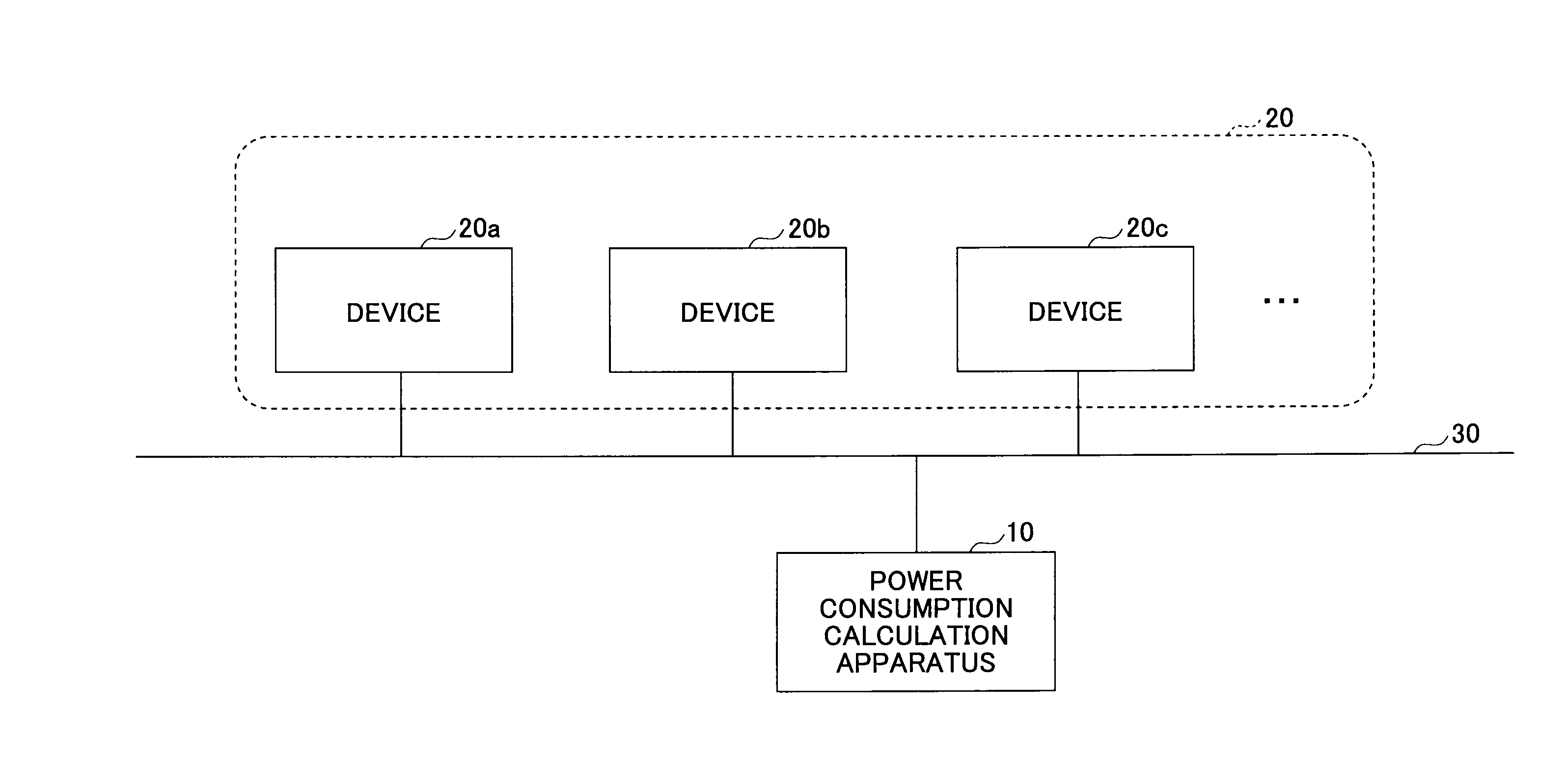
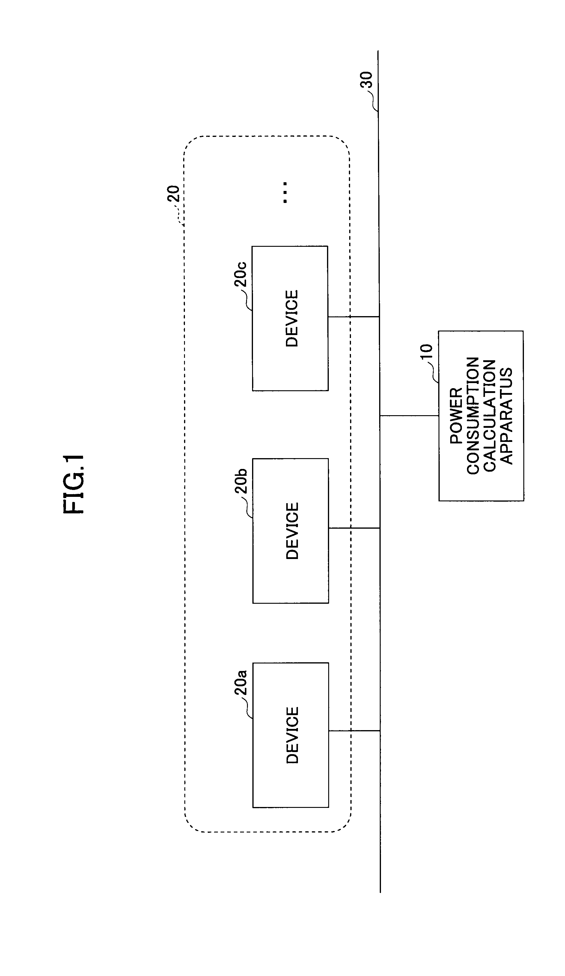
[0024]In the following, the present invention will be described with reference to the accompanying drawings. FIG. 1 is a diagram illustrating a configuration example of a power consumption calculation system according to the present invention. In FIG. 1, a power consumption calculation apparatus 10 is connected to one or more devices 20 (devices 20a, 20b, 20c, and the like) through a network 30 (wired or wireless) such as a LAN (Local Area Network).

[0025]The device 20 is an image forming apparatus such as a printer, a copier, a scanner, a facsimile, or a multi-functional apparatus which realizes two or more these functions in a single body. The power consumption calculation apparatus 10 is a computer which calculates (estimates) power consumption of each device 20.

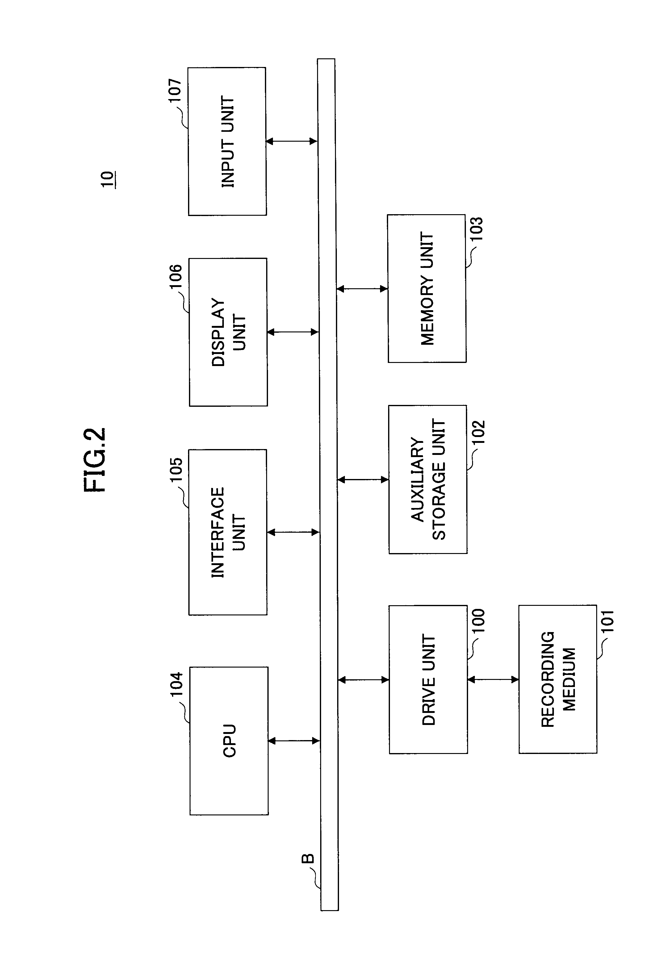
[0026]FIG. 2 is a diagram illustrating a configuration example of hardware of the power consumption calculation apparatus according to the first embodiment of the present invention. The power consumption calculation appara...

second embodiment

[0077]The job sending part 43 enters (sends) a job to the device 20. In the second embodiment, an example of entering a print job will be described. However, a type of a job is not limited to a specific type.

[0078]The power consumption value recording part 44 records the power consumption value received by the power consumption receiving part 42 and information indicating a relation to time when the power consumption value is received, to the power consumption value storage part 45. The power consumption value recording part 45 is a storage area in a memory unit, an auxiliary storage unit, or the like of the state transition data generation apparatus 40 for the power consumption.

[0079]The state transition detection part 46 detects the state transition (a segmentation of the state) of the device 20 based on the information recorded in the power consumption value storage part 45. The state transition data generation part 47 generates power consumption state transition data 48 based on...


PUM


Abstract

A power consumption calculation apparatus is disclosed, including: a work load measurement part, a management part, and a power consumption calculation part. The work load measurement part measures a work load of a job executed by an image forming apparatus and records a measured value, at predetermined time intervals. The management part manages state transition data indicating power consumption and a required time for each of states of the image forming apparatus which transits in response to an execution of each job. The power consumption calculation part calculates a power consumption amount corresponding to one job execution at each predetermined time interval when it is determined that the job is executed, based on the measured value and the state transition data.

Description

BACKGROUND OF THE INVENTION[0001]1. Field of the Invention[0002]The present invention is related to a power consumption calculation apparatus, a power consumption calculation method, and a state transition data generation method, and in particular to, the power consumption calculation apparatus, the power consumption calculation method, and the state transition data generation method, which calculate power consumption of an image forming apparatus.[0003]2. Description of the Related Art[0004]Recently, manufacturers and consumers have become more environmentally oriented and concerned more about energy savings, and awareness of the environment or the energy savings has been improved regarding an image forming apparatus (hereinafter, called “device”) such as a printer, a copier, or a multi-functional apparatus. For example, a device of lower power consumption is preferable on the market. Information concerning the power consumption of devices of major manufacturers is openly published...

Claims


Application Information

Patent Timeline
Patent Type & Authority Applications(United States)
IPC IPC(8): G01R21/00
CPCG01R22/10Y02B60/1267G03G15/55G06F1/3203G06F1/3284H04N1/00002H04N1/00015H04N1/00034H04N1/0005H04N1/00055H04N1/00061H04N1/00068H04N1/00127H04N2201/0039H04N2201/0082H04N2201/0091H04N2201/0094G03G15/5004Y02D10/00
Inventor MURATA, JUN
Owner RICOH KK
Why Eureka
Try Eureka