Manipulation simulator
- Summary
- Abstract
- Description
- Claims
- Application Information
AI Technical Summary
Benefits of technology
Problems solved by technology
Method used
Image

Examples
first embodiment
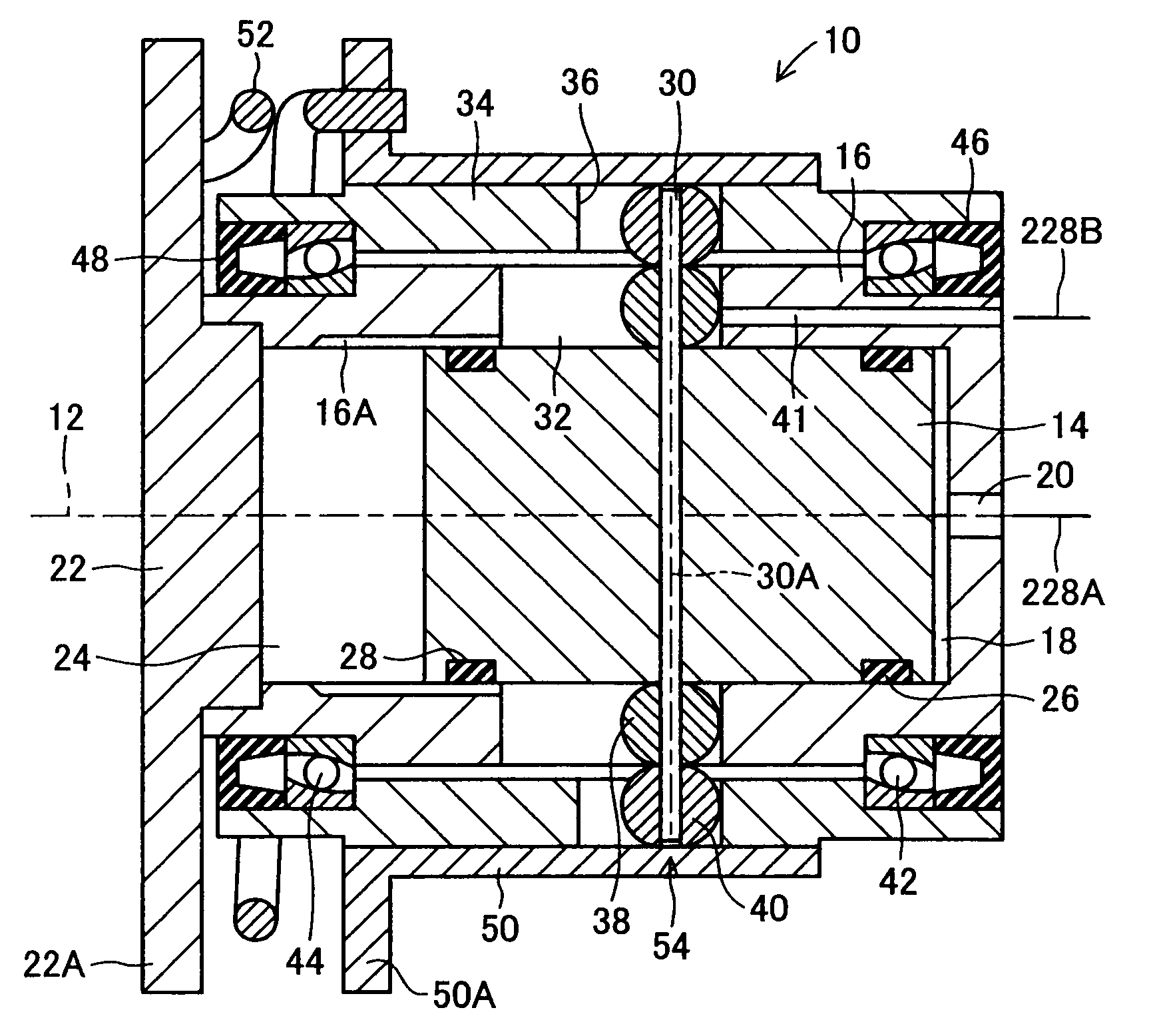
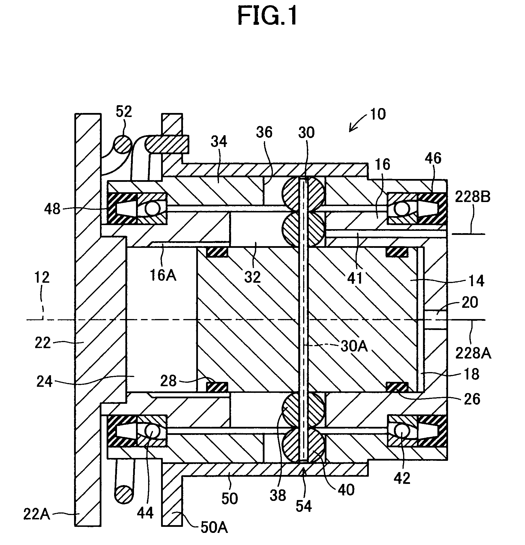
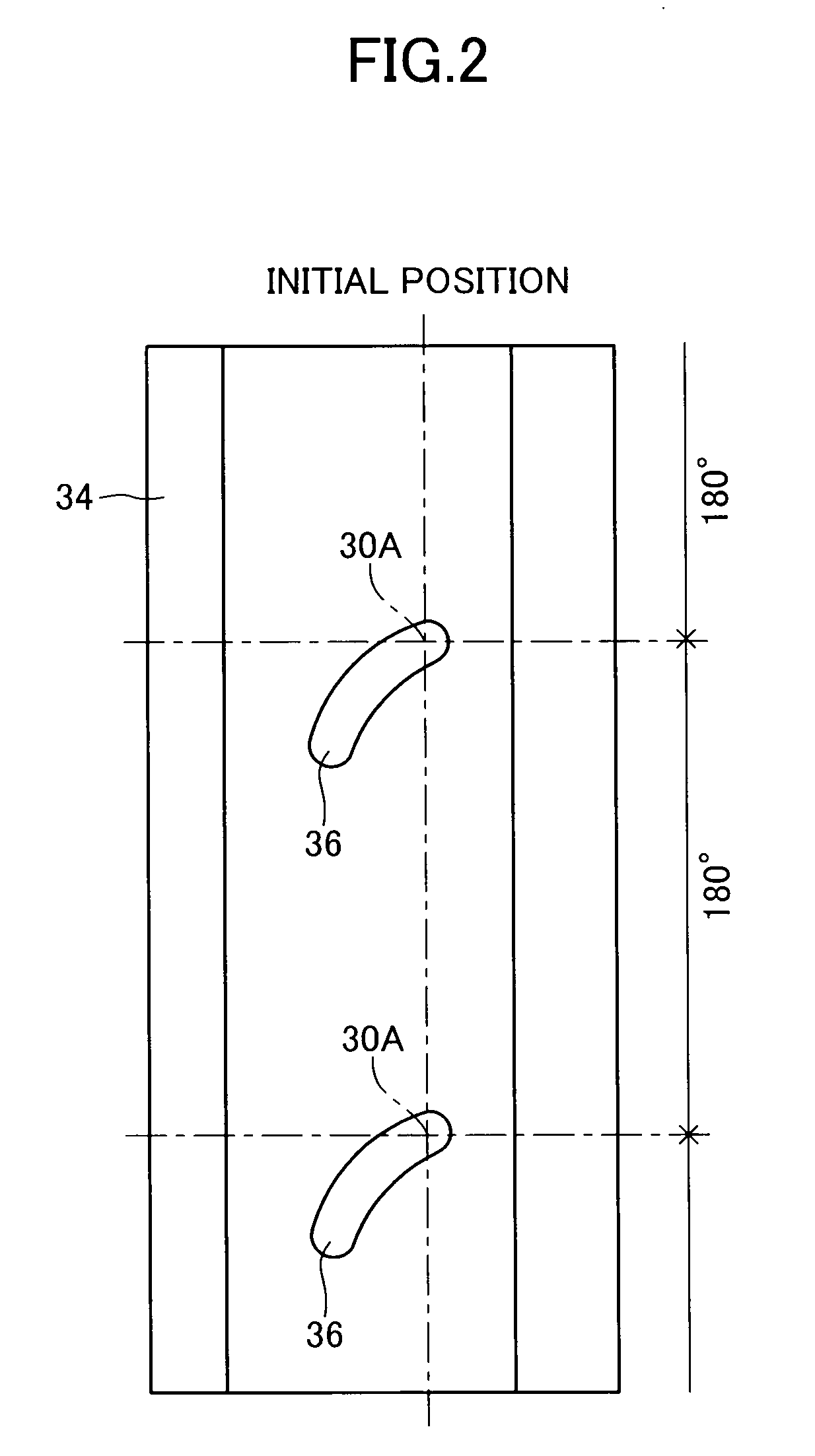
[0109]FIG. 1 is an axially-taken sectional view showing a first embodiment of a manipulation simulator according to the present invention and configured as a brake stroke simulator. FIG. 2 is a development view in which an output rotor of the first embodiment is developed on a plane.
[0110]In FIGS. 1 and 2, reference numeral 10 denotes the overall brake stroke simulator. The stroke simulator 10 has an input piston 14, which can move rectilinearly along an axis 12 and serves as an input member. The input piston 14 is supported in a cylindrical housing 16, which is opened at its one end, such that the input piston 14 can reciprocate along the axis 12. In cooperation with the housing 16, the input piston 14 defines a first cylinder chamber 18 whose volume is variable. The housing 16 has an end wall located at its other end, and a communication hole 20 is provided in the end wall. The first cylinder chamber 18 is connected to and communicates with a first master cylinder chamber 214A via...
second embodiment
[0130]FIG. 3 is an axially-taken sectional view showing a second embodiment of the manipulation simulator according to the present invention and configured as a brake stroke simulator. In FIG. 3, members similar to those shown in FIG. 1 are denoted by the same reference numerals appearing in FIG. 1.
[0131]In the second embodiment, the input piston 14 is supported at its base portion; i.e., at its end portion on a side toward the first cylinder chamber 18, by the housing 16 in such a manner as to be reciprocally movable along the axis 12. An O-ring seal 27 is attached to the inner wall surface of the housing 16, and rings corresponding to the antifriction rings 26 and 28 in the first embodiment are not provided. The input piston 14 is movably fitted to the housing 16 at its portion other than the base portion, and a spring chamber 58, which communicates with the second cylinder chamber 24, is defined between the housing 16 and the portion of the input piston 14. The spring chamber 58 ...
third embodiment
[0140]FIG. 4 is an axially-taken sectional view showing a third embodiment of the manipulation simulator according to the present invention and configured as a brake stroke simulator. FIG. 5 is a development view in which an output rotor of the third embodiment is developed on a plane. In FIGS. 4 and 5, members similar to those shown in FIGS. 1 and 2 are denoted by the same reference numerals appearing in FIGS. 1 and 2. This convention also applies to other embodiments to be described later.
[0141]In the third embodiment, an eccentric cam member 68 is fitted to the output rotor 34 from the radial outside and is fixed to the output rotor 34 by means of press fit or the like. The eccentric cam member 68 has a cylindrical outer surface whose axis 70 is parallelly deviated from the axis 12. The inner race of a ball bearing 72 is fixed to a small diameter portion of the eccentric cam member 68 while being in contact with a large diameter portion of the eccentric cam member 68. The outer r...
PUM
 Abstract
Description
Claims
Application Information
 - Generate Ideas
- Intellectual Property
- Life Sciences
- Materials
- Tech Scout
- Unparalleled Data Quality
- Higher Quality Content
- 60% Fewer Hallucinations
Browse by: Latest US Patents, China's latest patents, Technical Efficacy Thesaurus, Application Domain, Technology Topic, Popular Technical Reports.
© 2025 PatSnap. All rights reserved.Legal|Privacy policy|Modern Slavery Act Transparency Statement|Sitemap|About US| Contact US: help@patsnap.com