Component Placement Apparatus, Component Placement Setting Calculation Apparatus, Program, and Component Placement Setting Calculation Method

a technology of component placement and calculation method, which is applied in adaptive control, process and machine control, instruments, etc., can solve problems such as collisions among placement heads, and achieve the effect of preventing interference between multiple placement heads and one another

Active Publication Date: 2010-03-25
YAMAHA MOTOR CO LTD
View PDF5 Cites 7 Cited by
  • Summary
  • Abstract
  • Description
  • Claims
  • Application Information

AI Technical Summary

Benefits of technology

[0007]In view of the problem above, an object of the present invention is to provide a technique that avoids occurrence of interference among multiple placement heads, when multiple placement heads simultaneously access the circuit board and the pallet which is arranged in one direction with respect to the circuit board.
[0008]In order to solve the problem above, the present invention is directed to a configuration which avoids interference among the placement heads, when multiple placement heads pick up components from the pallet and place the components on the circuit board.
[0009]By way of example, the present invention is directed to a component placement apparatus in which multiple placement heads are allowed to operate simultaneously to pick up components from a pallet, and to place the components on the circuit board arranged in one direction with respect to the pallet, the component placement apparatus being provided with a controller to perform a processing, during one operation that the multiple placement heads pick up the components from the pallet and place the components on the circuit board, for specifying a pair of component groups to be simultaneously picked up from the pallet by the multiple placement heads so that an area where the multiple placement heads move in an overlapping manner is minimized, and a processing for allowing the placement heads to simultaneously provide operations to pick up the components included respectively in the component groups forming the pair, and to place the components being picked up on the circuit board.
[0010]As described above, according to the current invention, it is possible to prevent multiple placement heads from interfering with one another, when the multiple placement heads simultaneously access the circuit board and the pallet that is arranged in one direction with respect to the circuit board.

Problems solved by technology

If the technique described in the above document is employed for calculating the component placement setting in a component placement machine in which multiple placement heads access simultaneously the circuit board and the pallet arranged in one direction with respect to the circuit board, collision may occur among the placement heads, disabling an appropriate component placement.

Method used


Image

  • Component Placement Apparatus, Component Placement Setting Calculation Apparatus, Program, and Component Placement Setting Calculation Method
  • Component Placement Apparatus, Component Placement Setting Calculation Apparatus, Program, and Component Placement Setting Calculation Method
  • Component Placement Apparatus, Component Placement Setting Calculation Apparatus, Program, and Component Placement Setting Calculation Method

Examples


Embodiment Construction

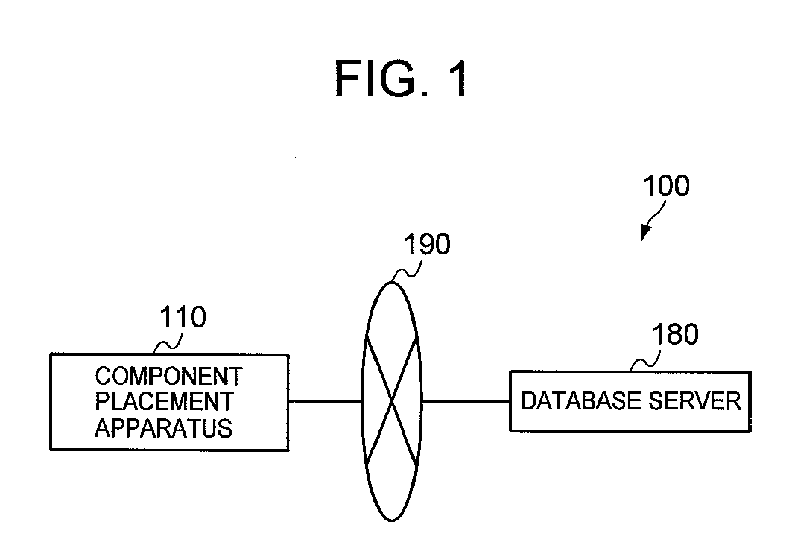
[0031]FIG. 1 schematically illustrates the component placement system 100 according to one embodiment of the present invention. As illustrated, the component placement system 100 is provided with a component placement apparatus 110 and a database server 180, and the component placement apparatus 110 and the database server 180 are allowed to mutually exchange information via a network.

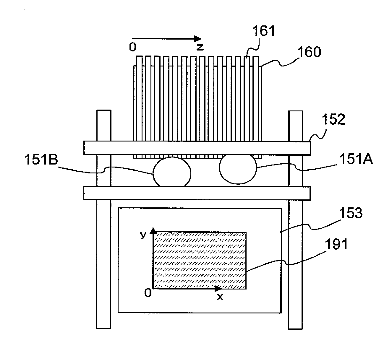
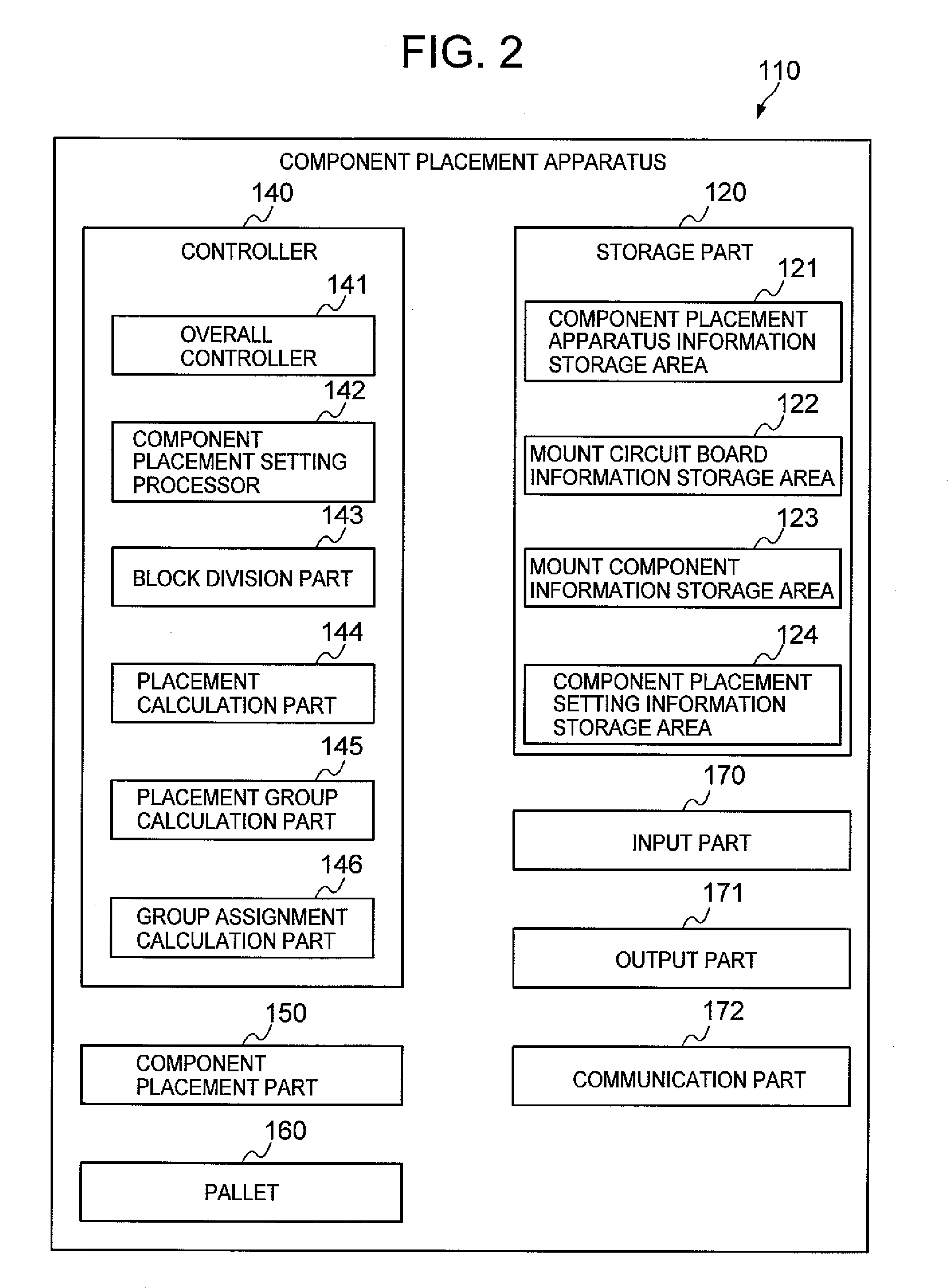
[0032]FIG. 2 schematically illustrates the component placement apparatus 110. As illustrated, the component placement apparatus 110 is provided with a storage part 120, a controller 140, a component placement part 150, a pallet 160, an input part 170, an output part 171, and a communication part 172.

[0033]The storage part 120 is provided with a component placement apparatus information storage area 121, a mount circuit board information storage area 122, a mount component information storage area 123, and a component placement setting information storage area 124.

[0034]The component placement apparatus...


PUM

PropertyMeasurementUnit
weightaaaaaaaaaa
areaaaaaaaaaaa
widthaaaaaaaaaa

Abstract

The present invention is directed to a technique that avoids occurrence of interference among multiple placement heads, when multiple placement heads simultaneously access a circuit board, and a pallet which is arranged in one direction with respect to the circuit board. When the component placement part 150 having the multiple placement heads simultaneously pick up the components from the pallet 160 and simultaneously place the components on the circuit board, the controller 140 specifies a pair of component groups to be picked up simultaneously from the pallet 160 by the multiple placement heads and places the components on the circuit board, so that an area where the multiple placement heads move in overlapping manner is minimized, and the placement heads respectively pick up the components included in the pair of component groups being specified and place the components on the circuit board.

Description

BACKGROUND OF THE INVENTION [0001]1. Field of the Invention[0002]The present invention relates to a technique in which multiple placement heads pick up components from a pallet, and place the components on a circuit board located in one direction with respect to the pallet.[0003]2. Description of the Related Art[0004]In a component placement apparatus, in which a placement head, which moves between a component pickup position and a component placement position, picks up a component located at a component supply position (component pickup position), transports and places the component on a circuit board at the component placement position, it is necessary to generate in advance a component placement setting, such as a mounting position on a component supply tray (hereinafter, referred to as a “pallet”) of a component supply unit storing component to be placed on the circuit board, components pickup sequencing by the placement head, and placement sequencing.[0005]By way of example, “A...

Claims


Application Information

Patent Timeline
Patent Type & Authority Applications(United States)
IPC IPC(8): B23P19/00
CPCY10T29/53174H05K13/0478H05K13/02H05K13/04
Inventor CHIDA, TAKAFUMINAKANO, TAKAHIROIZUHARA, KOICHITSUJIMOTO, YOSHIYUKI
Owner YAMAHA MOTOR CO LTD
Why Eureka
Try Eureka