
Spiral Cooled Fuel Nozzle

a fuel nozzle and spiral cooling technology, applied in the direction of machines/engines, mechanical equipment, lighting and heating apparatus, etc., can solve the problems of additional parasitic loss, affecting the overall plant efficiency, and adding to the complexity of gas turbine engines

Inactive Publication Date: 2010-03-25
SIEMENS ENERGY INC
View PDF14 Cites 30 Cited by
  • Summary
  • Abstract
  • Description
  • Claims
  • Application Information

AI Technical Summary

Benefits of technology

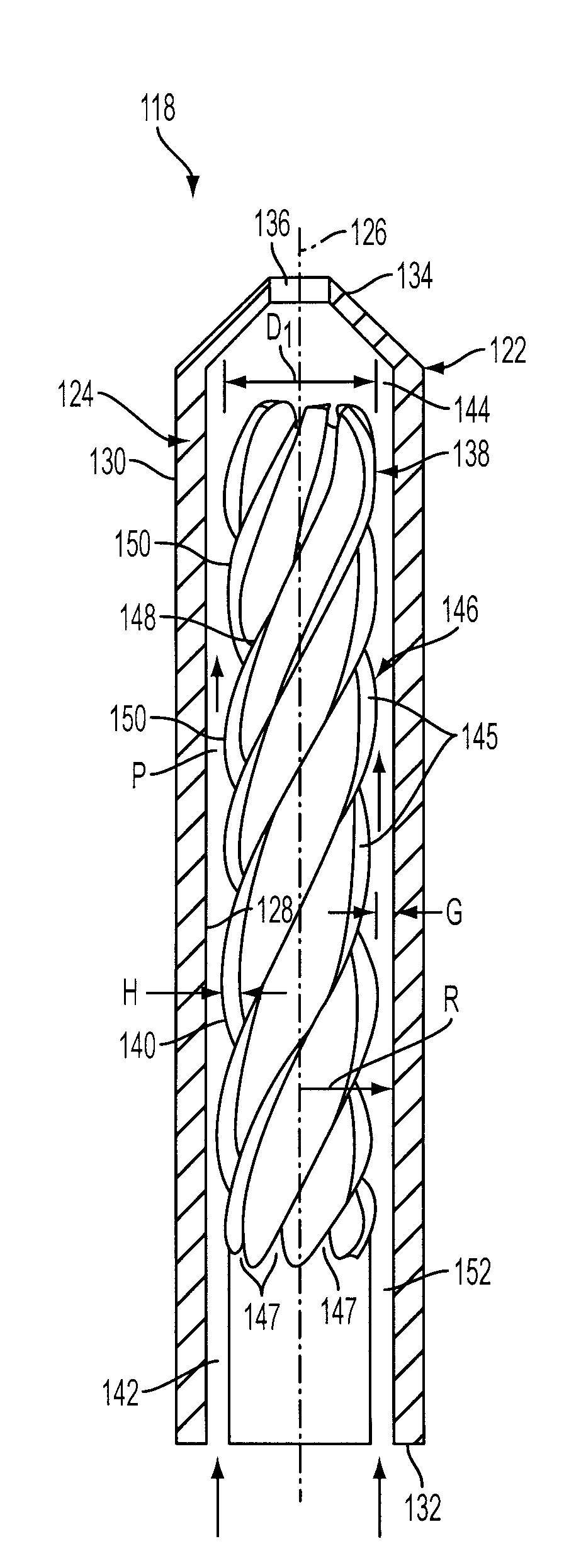
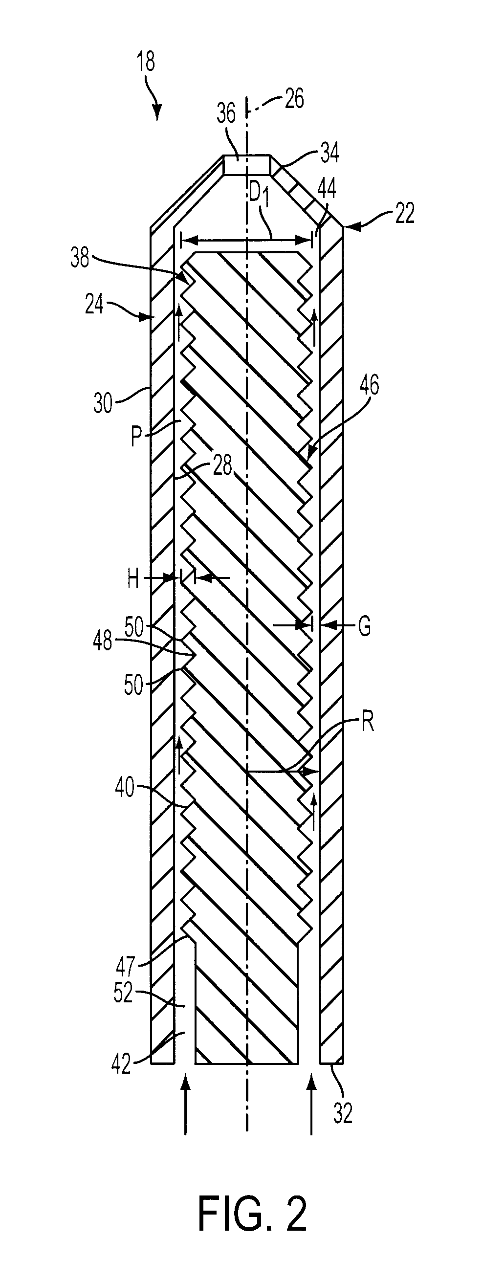
[0006]In accordance with one aspect of the invention, a fuel nozzle is provided for delivery of fuel to a gas turbine engine. The fuel nozzle comprises a tubular nozzle member comprising an outer nozzle wall defining a longitudinal axis. The nozzle wall includes an inner wall surface and an outer wall surface and has a fuel inlet end and a fuel outlet end. The fuel nozzle further comprises a center body including an outer body surface. The center body has a longitudinal axis that is substantially collinear with the longitudinal axis of the nozzle wall. A gap is defined between the inner wall surface and the outer body surface and extends circumferentially about the outer body surface for providing fuel flow in a longitudinal direction from an upstream end adjacent to the inlet end to a downstream end adjacent to the outlet end. The gap is effective to provide a substantially uniform temperature distribution along the nozzle wall in the circumferential direction.
[0007]In accordance with another aspect of the invention, a fuel nozzle is provided for delivery of fuel to a gas turbine engine. The fuel nozzle comprises a tubular nozzle member comprising an outer nozzle wall defining a longitudinal axis. The nozzle wall includes an inner wall surface and an outer wall surface and has a fuel inlet end and a fuel outlet end. The fuel nozzle further comprises a center body including an outer body surface. The center body has a longitudinal axis that is substantially collinear with the longitudinal axis of the nozzle wall. A gap is defined between the inner wall surface and the outer body surface and extends circumferentially about the outer body surface for providing fuel flow in a longitudinal direction from an upstream end adjacent to the inlet end to a downstream end adjacent to the outlet end. A turbulating feature is located adjacent to the gap for causing at least a portion of the fuel flow along the length of the gap to flow transverse to the longitudinal direction. The gap is effective to provide a substantially uniform temperature distribution along the nozzle wall in the circumferential direction.

Problems solved by technology

The delivery of such diluents with the fuel adds to the complexity, with associated costs, of the gas turbine engine.
In addition, when air is used as a diluent, the compressor for supplying the air represents an additional parasitic loss that affects the overall plant efficiency.

Method used


Image

  • Spiral Cooled Fuel Nozzle
  • Spiral Cooled Fuel Nozzle
  • Spiral Cooled Fuel Nozzle

Examples


Embodiment Construction

[0014]In the following detailed description of preferred embodiments, reference is made to the accompanying drawings that form a part hereof, and in which is shown by way of illustration, and not by way of limitation, specific preferred embodiments in which the invention may be practiced. It is to be understood that other embodiments may be utilized and that changes may be made without departing from the spirit and scope of the present invention.

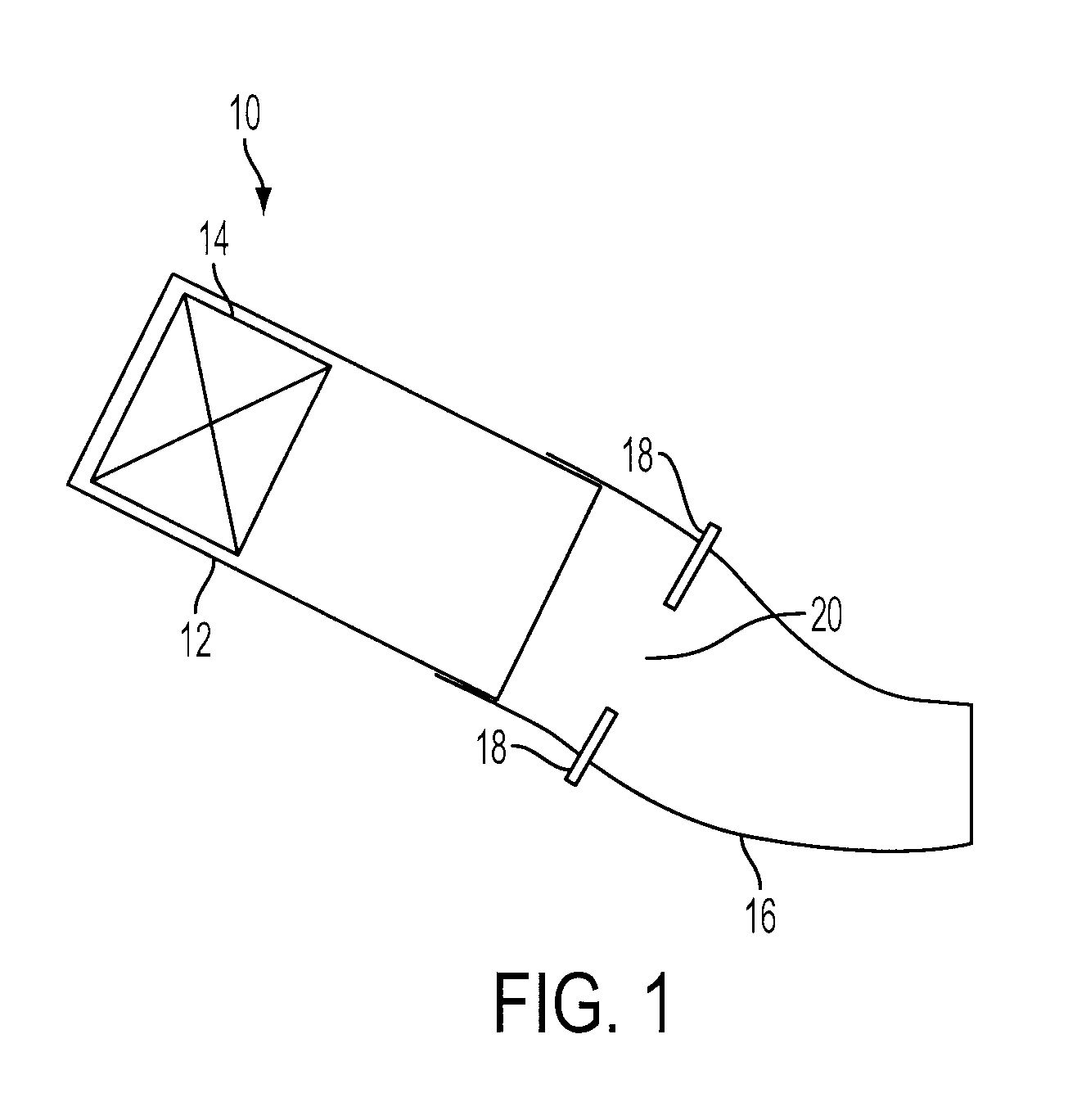
[0015]Referring to FIG. 1, a can combustor 10 for a gas turbine engine is illustrated including a combustor case 12 and a primary combustor 14. The primary combustor 14 includes structure for receiving air from a compressor section (not shown) of the engine and fuel injectors (not shown) for injecting fuel for combustion within the combustor case 12, as is known in the art. A transition piece 16 is located at an outlet end of the combustor case 12 for receiving hot products of combustion exiting the combustor case 12 and for directing the ho...


PUM


Abstract

A fuel nozzle for delivery of fuel to a gas turbine engine. The fuel nozzle includes an outer nozzle wall and a center body located centrally within the nozzle wall. A gap is defined between an inner wall surface of the nozzle wall and an outer body surface of the center body for providing fuel flow in a longitudinal direction from an inlet end to an outlet end of the fuel nozzle. A turbulating feature is defined on at least one of the central body and the inner wall for causing at least a portion of the fuel flow in the gap to flow transverse to the longitudinal direction. The gap is effective to provide a substantially uniform temperature distribution along the nozzle wall in the circumferential direction.

Description

[0001]This invention was made with U.S. Government support under Contract Number DE-FC26-05NT42644 awarded by the U.S. Department of Energy. The U.S. Government has certain rights to this invention.FIELD OF THE INVENTION[0002]The present invention relates to gas turbine engines and, more particularly, to fuel nozzles for use in gas turbine engines.BACKGROUND OF THE INVENTION[0003]In gas turbine engines, fuel is delivered from a source of fuel to a combustion section where the fuel is mixed with air and ignited to generate hot combustion products defining working gases. The working gases are directed to a turbine section. The combustion section may comprise one or more stages, each stage supplying fuel to be ignited. It has been found that the production of NO gases from the burning fuel can be reduced by providing fuel downstream from a main combustion zone.[0004]A prior art method of delivering fuel to the downstream combustion zone of the combustion section is illustrated in U.S. ...

Claims


Application Information

Patent Timeline
Patent Type & Authority Applications(United States)
IPC IPC(8): F02C7/22B05B1/00
CPCF02C7/22F23R3/28F05D2260/20F05D2250/25F23R3/34
Inventor FOX, TIMOTHYSCHILP, REINHARD
Owner SIEMENS ENERGY INC
Features
  • Generate Ideas
  • Intellectual Property
  • Life Sciences
  • Materials
  • Tech Scout
  • Unparalleled Data Quality
  • Higher Quality Content
  • 60% Fewer Hallucinations
Learn More