Supercavitating vehicle control

a supercavitating vehicle and control system technology, applied in the direction of vessel movement reduction, vessel construction, foiling, etc., can solve the problems of intermittent banging of the tail surface, aft vehicle control system producing considerable parasitic drag, and vapor cavity may collapse about the trailing portions of the vehicle, etc., to achieve steady lift

Inactive Publication Date: 2010-03-25
UNITED STATES OF AMERICA NAVAL UNDERSEA WARFARE CENT DIV NEWPORT OFFICE OF COUNSEL THE
View PDF6 Cites 12 Cited by
  • Summary
  • Abstract
  • Description
  • Claims
  • Application Information

AI Technical Summary

Benefits of technology

[0020]In another variation, ring struts each may have a first end connected to the vehicle and a distal end pivotally connected to one of the segments of the ring wing. Ring actuators each may be connected to one of the ring struts and a corresponding one of the segments. Opera...

Problems solved by technology

However, if the speed of the vehicle is not sufficiently fast, the vapor cavity may collapse about the trailing portions of the vehicle.
However, the existing system of aft vehicle control produces considerable parasitic drag.
In addition, such systems create contin...

Method used


Image

  • Supercavitating vehicle control
  • Supercavitating vehicle control
  • Supercavitating vehicle control

Examples


Embodiment Construction

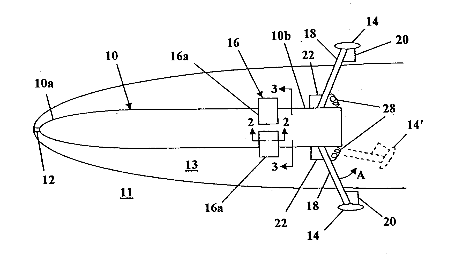
[0030]Referring now to FIG. 1, there is shown a side view of underwater vehicle 10 traversing through a fluid medium 11. For ease of reference, medium 11 is described herein as water. As is known in the art, water 11 is accelerated over a cavitator 12 attached to a nose portion 10a of vehicle 10. The downstream pressure drops below the vapor pressure of water 11 after passing cavitator 12, resulting in the formation of cavity 13, through which vehicle 10 traverses.

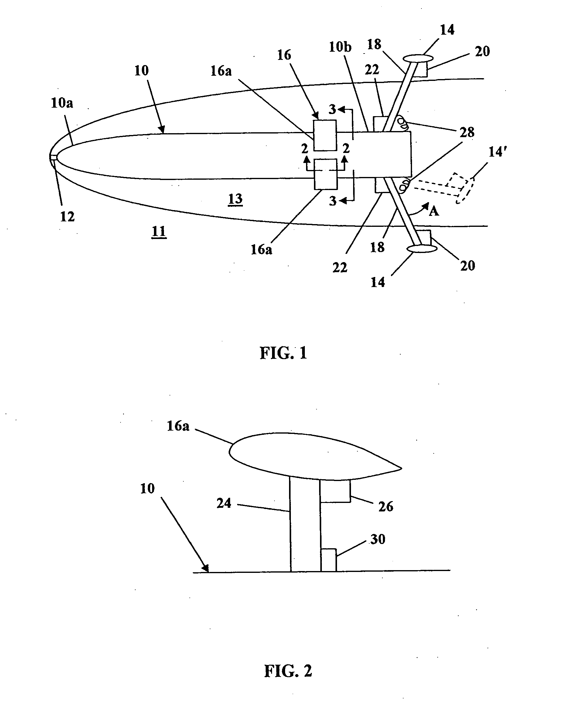
[0031]For stability and control of vehicle 10, winglets 14 and segmented ring wing 16 extend from an aft portion 10b of vehicle 10. In the side view of FIG. 1, two winglets 14 and two segments 16a of ring wing 16 are illustrated. However, those of skill in the art will recognize that the number of winglets 14 and segments 16a can be varied; with the winglets 14 and segments 16a being spaced equally about vehicle 10 for maintaining balance. Thus, for balance purposes but not for limitation, at least two winglets 14 and at l...


PUM


Abstract

A control system for a supercavitating vehicle includes a set of winglets for rapid maneuverability and a segmented ring wing for fine stabilization control. The winglets and ring wing extend from an aft portion of the vehicle. The winglets are supported by a strut attached to the vehicle. The angle of attack of each winglet into the water adjacent the cavity is controlled by a winglet actuator. The winglet assembly may be extended into the water or retracted to be completely within the cavity by means of a spring-loaded actuated mount. The segmented ring wing is controlled by a ring actuator. The ring actuator may be used to control the angle of attack of the ring wing. Alternately, or in combination, the flow over the ring wing may be neutralized by using the cavitator of the vehicle to globally enlarge the cavity and thus limit the flow.

Description

STATEMENT OF GOVERNMENT INTEREST[0001]The invention described herein may be manufactured and used by or for the Government of the United States of America for governmental purposes without the payment of any royalties thereon or therefor.CROSS REFERENCE TO OTHER PATENT APPLICATIONS[0002]Not applicable.BACKGROUND OF THE INVENTION[0003](1) Field of the Invention[0004]The present invention relates to vehicle control systems and methods and more specifically to systems and methods for controlling a trajectory of a supercavitating vehicle.[0005](2) Description of the Prior Art[0006]There exists a need for reducing drag in underwater vehicles, such as torpedoes, so as to enhance their speed, reliability and stealthy operation. For a nominally streamlined, fully wetted underwater vehicle, 80% of the overall drag is skin friction drag. The remaining drag is pressure or blockage drag.[0007]Some investigations into reducing the drag of high-speed, underwater vehicles have focused attention on...

Claims


Application Information

Patent Timeline
IPC IPC(8): B63H25/00
CPCB63B39/06B63H25/06B63H25/00B63B39/062
Inventor KUKLINSKI, ROBERT
Owner UNITED STATES OF AMERICA NAVAL UNDERSEA WARFARE CENT DIV NEWPORT OFFICE OF COUNSEL THE
Why Eureka
Try Eureka