Traveling mechanism for agricultural machines and off-road vehicles having an endless belt-band traveling gear and a corresponding belt-band traveling gear

a technology of traveling gear and agricultural machinery, which is applied in the direction of conveyors, transportation and packaging, shock absorbers, etc., can solve the problems of reduced tire load, inability to support the vehicle, and inability to maneuver, so as to achieve low travel speed, poor maneuverability, and high wear of belts

Active Publication Date: 2010-03-25
DEERE & CO
View PDF0 Cites 12 Cited by
  • Summary
  • Abstract
  • Description
  • Claims
  • Application Information

AI Technical Summary

Benefits of technology

[0010]A priority objective of the present invention is to avoid the afore-mentioned disadvantages and to provide a belt-band traveling gear, which enables a more uniform ground loading and additionally offers increased driving and rolling comfort.
[0018]Furthermore, in a preferred variant of the present invention, the supporting rollers are each suspended or mounted so as to enable a definite twist of the preferably resilient belt. This can be possible by means of a suitable swivelability of the rotation axes of the supporting rollers about a real or virtual swivel axis oriented approximately parallel to the longitudinal direction of the vehicle. In a sufficiently resilient belt, it is possible in this manner to prevent the belt from digging into the ground with only one load-bearing edge in the case of a greatly uneven ground. The pivoting angle of the supporting rollers can be limited, if necessary, in order to reliably prevent the belt from wearing.
[0023]In another design form according to the present invention, an accumulator—usually a hydropneumatic reservoir—can be connected to the mutually supporting cylinder system to form a fluidic coupling. Thus, a springy effect is also achieved advantageously and a corresponding belt-band traveling gear is decoupled from the associated vehicle frame, so that the highest driving and rolling comfort is possible.
[0028]Another advantage is achieved according to the present invention by decoupling the supporting cylinders and impinging the rotatably mounted carrier rollers by a pressure source deliberately so that these carrier rollers are loaded or relieved of load accordingly. Thus it can be advantageous, e.g. on a side slope, to shorten the contact surface of the bogie by loading the middle carrier rollers more heavily than the front and rear carrier rollers so as to largely be able to prevent a lateral slippage on the slope. This variant also can be equipped in turn with or without suspension.
[0029]The belt-band traveling gear according to the present invention is particularly suitable for self-propelling agricultural work machines, for forest machines and construction machines and also for other commercial vehicles and transport vehicles, which can be used on soft, resilient and / or uneven grounds and also on impassable terrains. The advantages of the vehicles having conventional wheeled traveling mechanisms, namely their flexibility, their relatively good maneuverability and the relatively high travel speed are predominantly influential during on-road operation or when traveling on paved dry grounds. In contrast, wheeled traveling gears reach their limits in the case of very high vehicle weights.
[0031]In addition, the belt-band traveling gear according to the present invention enables a very easily realizable, automatically controllable or manually adjustable slope compensation since a certain inclination can be compensated during travel uphill or downhill by a corresponding pressurization of the traveling gear supporting cylinders. A camber compensation of the vehicle body can be achieved in an additional gimbal-mounted suspension or any other suitable suspension of the bogie preferably on the left and right side each independent of the other. This firstly leads to an improved driving comfort and secondly an increased tilt resistance and improved traction.

Problems solved by technology

These high surface pressures can lead to an impermissibly high soil compaction especially in wet farmlands.
Even a reduced internal pressure of tires cannot change much about this problem since in the case of a clearly reduced tire pressure as would be desirable per se for traveling on soft or wet farmlands, the load on the tires is reduced as a result of which the weight of the vehicle can no longer be supported.
The typical disadvantage of these rigidly mounted deflection rollers is a very limited driving and rolling comfort as compared to a wheeled traveling mechanism, particularly during on-road operation.
An additional serious disadvantage of the traveling gears known from prior art is that the resulting contact loads cannot be distributed uniformly on all the carrier and deflection rollers.
However, if one carrier roller runs on a bump, the carrier roller is overloaded and the load on the other carrier rollers is relieved resulting in turn in high loads on the grounds.
However, they do not enable any uniform pressure distribution over the entire length of the traveling gear, as a result of which very high pressure peaks are transmitted partially in the farmlands even in the case of traveling mechanisms known from prior art.

Method used


Image

  • Traveling mechanism for agricultural machines and off-road vehicles having an endless belt-band traveling gear and a corresponding belt-band traveling gear
  • Traveling mechanism for agricultural machines and off-road vehicles having an endless belt-band traveling gear and a corresponding belt-band traveling gear
  • Traveling mechanism for agricultural machines and off-road vehicles having an endless belt-band traveling gear and a corresponding belt-band traveling gear

Examples


Embodiment Construction

[0033]The present invention shall now be explained in detail on the basis of a preferred exemplary embodiment with reference to the attached drawings. The example serves for illustrating the invention. However, it is by no means to be construed as a restriction of the invention. Identical parts and parts performing identical functions are denoted by the same reference numerals; repeat explanations have been avoided to some extent.

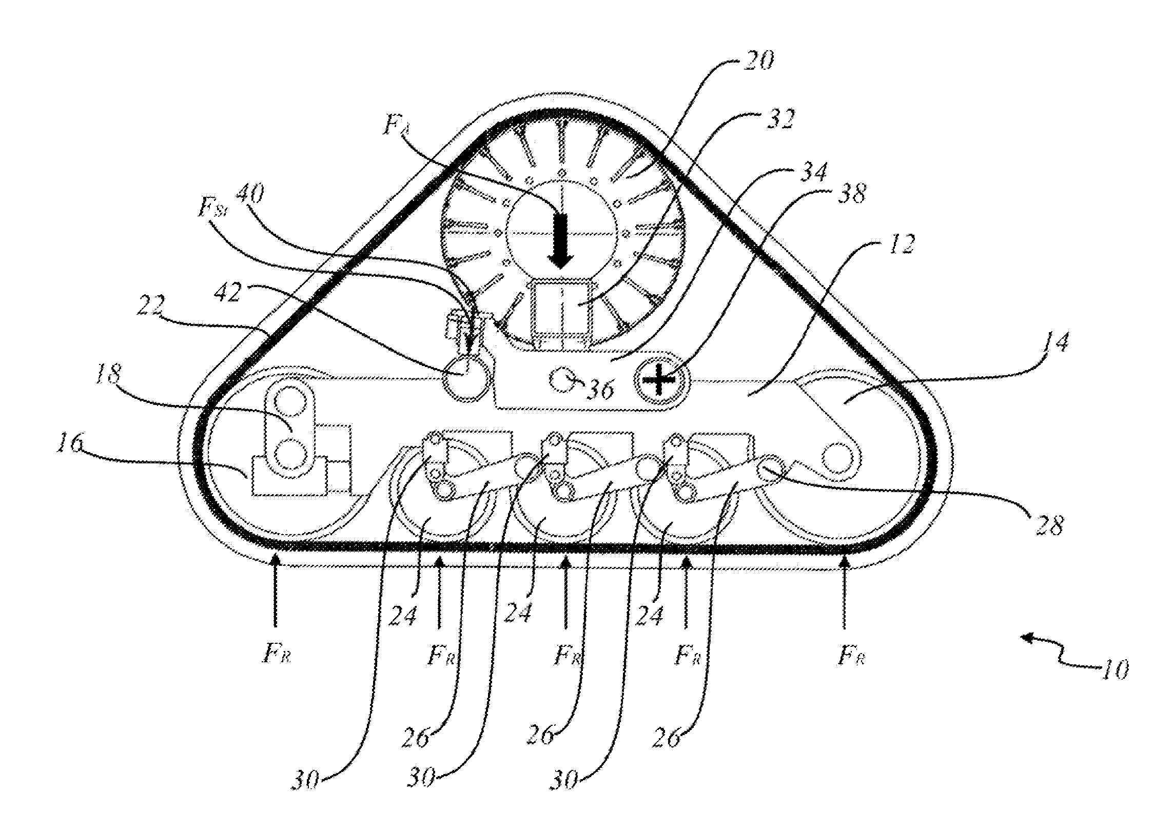
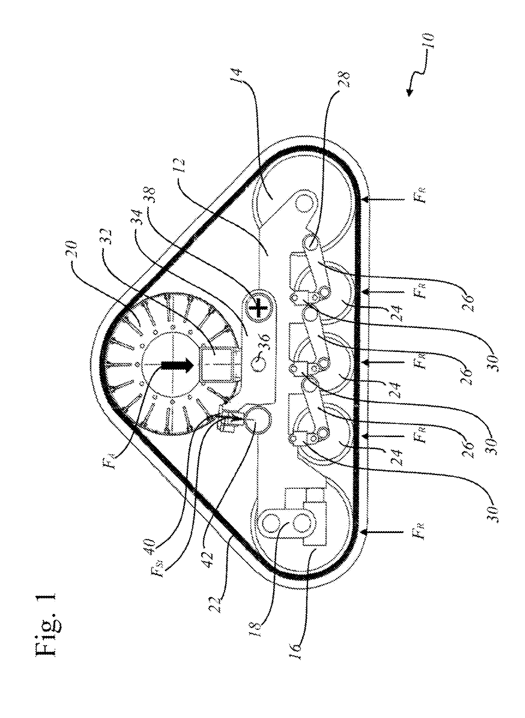
[0034]FIG. 1 shows a schematic drawing of a basic structure of a variant of the belt-band traveling gear according to the present invention.

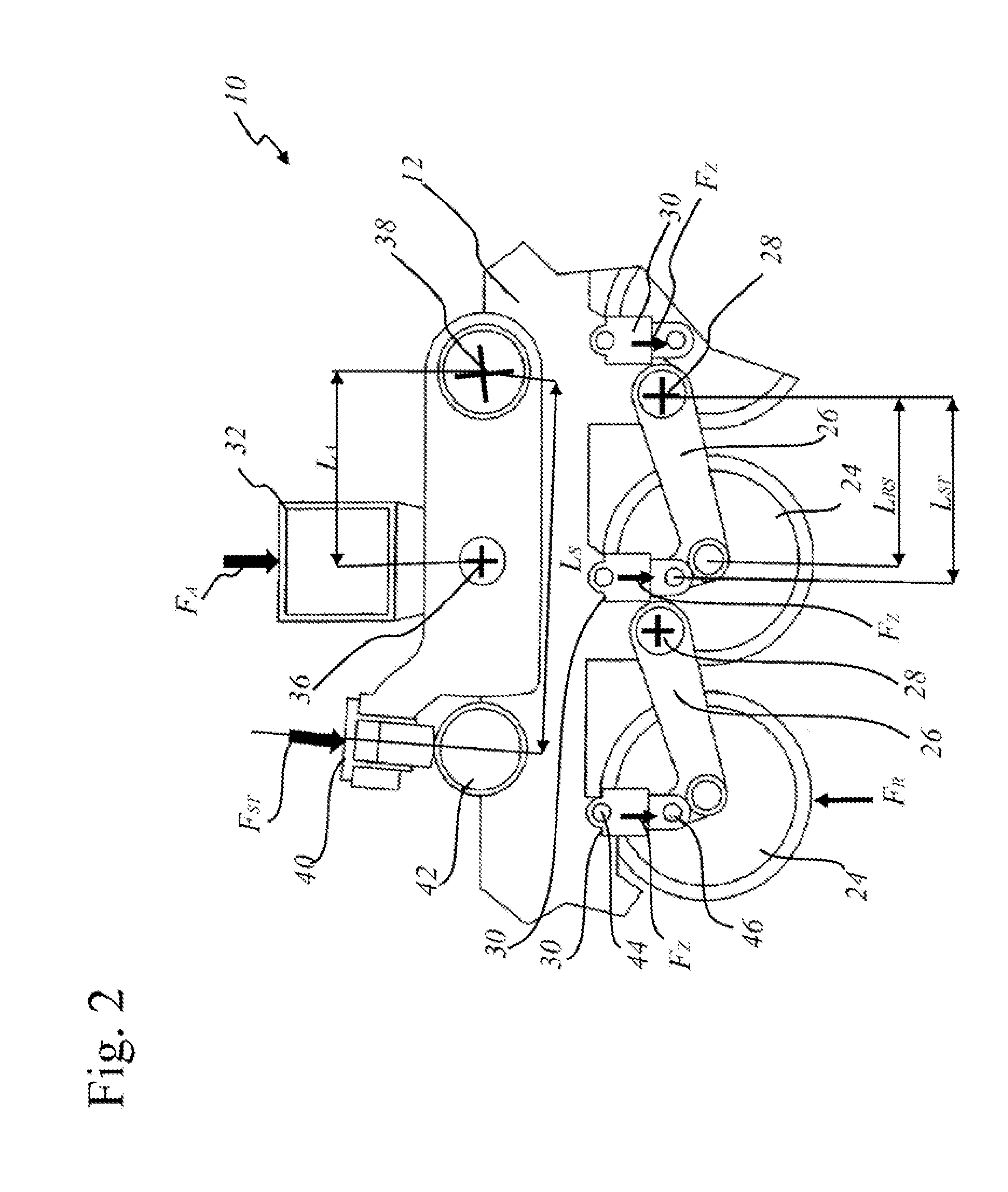
[0035]FIG. 2 shows a schematic drawing of a section of the basic structure of the belt-band traveling gear shown in FIG. 1.

[0036]FIG. 3 shows a schematic sectional view of the belt-band traveling gear.

[0037]FIG. 4 shows a lateral view of another variant of the belt-band traveling gear.

[0038]FIG. 5 shows a possible structure of the piping of a fluidic coupling for connecting the elements of the belt-band traveling gear b...


PUM


Abstract

The invention relates to a spring-suspended, bearing force-optimized belt-band traveling gear (10) for ground vehicles, particularly for self-propelled agricultural machines and other off-road vehicles, comprising at least two outer deflection rollers (14, 15, 16, 17) over whose periphery an endless belt-band (22) rolls off, and at least one supporting roller (24) for supporting the belt-band section, which is in contact with the ground, between both deflection rollers (14, 15, 16, 17). A bogie truck (12, 13), in which the at least two deflection rollers (14, 15, 16, 17) are mounted in a manner that enables them to rotate, is supported against a body frame of the vehicle by means of a first fluidic suspension unit and / or damping unit. The at least one supporting roller (24) is supported on the bogie truck (12, 13) by means of a second fluidic suspension unit and / or damping unit. A fluidic coupling of the suspension units and / or damping units of the bogie truck (12, 13) is provided against the vehicle frame and the at least one supporting roller (24) mounted on the bogie truck (12, 13).

Description

CROSS-REFERENCE TO RELATED PATENT APPLICATION[0001]This application is a continuation of U.S. patent application Ser. No. 11 / 659,865, filed Feb. 9, 2007, which application is hereby incorporated by reference in its entirety.FIELD OF THE INVENTION[0002]The present invention relates to a traveling mechanism for agricultural machines and off-road vehicles having an endless belt-band traveling gear. The invention further relates to a belt-band traveling gear, particularly a spring-mounted, belt-band traveling gear with optimum bearing strength specifications, the belt-band traveling gear being suitable inter alia for self-propelled agricultural machines and other off-road vehicles. Furthermore, the invention relates to a ground vehicle having a spring-mounted belt-band traveling gear with optimum bearing strength specifications.BACKGROUND OF THE INVENTION[0003]Ground vehicles used in agriculture usually comprise pneumatic tires, which create the interface to the ground. The tires have t...

Claims


Application Information

Patent Timeline
Patent Type & Authority Applications(United States)
IPC IPC(8): B62D55/065B62D55/10F16F9/34
CPCB62D55/112B62D55/14B62D55/1125B60G2206/011
Inventor RAINER, JOHANN
Owner DEERE & CO
Why Eureka
Try Eureka